20
Safety Relay MINOS SD1E
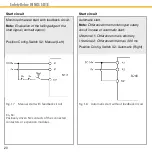
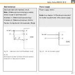
Fig. 17
Manual start with feedback circuit
K
A
, K
B
:
Positively driven NC contacts of the connected
contactors or expansion modules.
Start circuit
Monitored manual start with feedback circuit.
Note:
Evaluation of the falling edge of the
start signal (contact opens).
Position Config-Switch S2: Manual (Left)
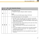
Start circuit
Automatic start.
Note:
Difference time monitoring at safety
circuit in case of automatic start:
I2 before I1: Difference time
is arbitrary
I1 before I2: Difference time max. 300 ms
Position Config-Switch S2: Automatic (Right)
Fig. 18
Automatic start without feedback circuit
Summary of Contents for MINOS SD1E
Page 1: ...Operating Instructions Safety Relay MINOS SD1E MINOS SD1E...
Page 23: ...23 Safety Relay MINOS SD1E EN...
Page 36: ...36 Safety Relay MINOS SD1E 24 Declaration of Conformity...
Page 37: ...37 Safety Relay MINOS SD1E EN...
Page 39: ...39 Safety Relay MINOS SD1E EN...
Page 40: ...40 Safety Relay MINOS SD1E...


