8
Safety Relay MINOS SD1E
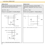
For example:
For a two channel application with cross
circuit monitoring and automatic start the
Config-Switches must be set as follows:
Config-Switch
S1
: Left (Enabled)
Config-Switch
S2
: Right (Automatic)
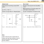
Safety circuit I1 / I2:
The safety circuit is designed to be used as
single or dual channel via I1 and I2 depending
on the wiring and the position of the Config-
Switch S1 (see chapter 12 “Commissioning”).
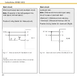
Start input S21:
A monitored, manual start or an automatic
start is provided via the terminal S21. The
start function can be set via the Config-Switch
S2 on the back of the device. (see chapter 12;
“Commissioning”).
Safe relay contact 13-14:
Considering the start behaviour, the safe
relay contact switches on at the time the
safety circuit closes. Opening the safety
circuit results in an immediate shutdown (safe
condition).
Auxiliary output C1:
The PNP-semiconductor output switches
invertedly to the safe relay contact and may
not be used as safe output.
Behaviour in case of a fault:
It is ensured that one single fault does not
lead to loss of the safety function and that
every fault is detected latest when the system
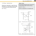
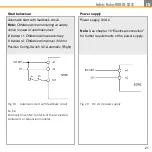
Fig. 2
Block diagram SD1E
Fig. 1
Configurationtable SD1E
Summary of Contents for MINOS SD1E
Page 1: ...Operating Instructions Safety Relay MINOS SD1E MINOS SD1E...
Page 23: ...23 Safety Relay MINOS SD1E EN...
Page 36: ...36 Safety Relay MINOS SD1E 24 Declaration of Conformity...
Page 37: ...37 Safety Relay MINOS SD1E EN...
Page 39: ...39 Safety Relay MINOS SD1E EN...
Page 40: ...40 Safety Relay MINOS SD1E...


