background image

56 


3.


Beschreibung der Maschine 

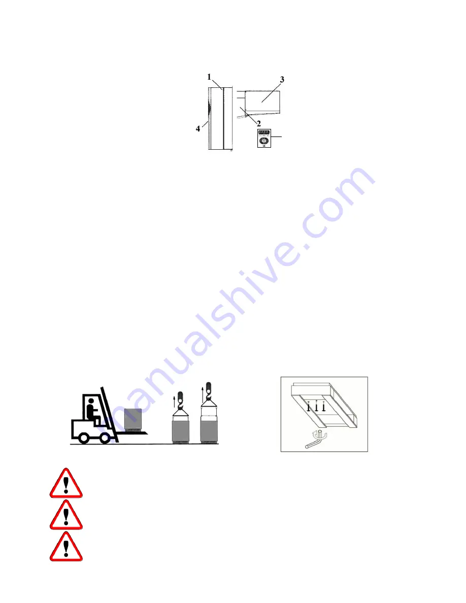
Die Kühlanlagen der GM-Serie sind mit luft- oder wassergekühlten Kondensatoren (wahlweise) ausgestattet. Sie 

werden in Monoblock-Ausführung hergestellt und bestehen aus: 


1.


einer außerhalb der Zelle installierten Kondensierungseinheit 

2.


einem Isolierstopfen (wahlweise) für die Wandmontage an Stelle der 

Huckepackmontage 

3.


einem in der Zelle installierten Verdampferteil. 

4.


einer  elektrische  Kontroll-  und  Steuerschalttafel  auf  der 

Kondensierungseinheit 

5.


Fernbedienung (wahlweise) an der Wand befestigt 


4.


Betrieb der Maschine 


Die  Uniblock GM sind Kompressionskühlgruppen, in denen die Kälte durch Verdampfung einer 

kälteerzeugenden Flüssigkeit vom Typ HFC bei niedrigem Druck in einem Wärmeaustauscher (Verdampfer) 

erzeugt wird; der so erzeugte Dampf wird durch mechanische Kompression bei einem höheren Druck erneut 

verflüssigt, gefolgt von einer Kühlung in einem anderen Wärmeaustauscher (Kondensator). Der Kühlkompressor 

ist hermetischer Art, mit abwechselnder Bewegung und wird  von einem Ein-  oder Dreiphasen-Stromnetz 

versorgt. Die Enteisung mittels Einspritzung von warmem Gas (Standard) oder elektrischer Widerstände 

(wahlweise) wird je nach Notwendigkeit nach automatischer Vorprogrammierung in regelmäßigen Abständen 

durchgeführt, dabei besteht die Möglichkeit von manuellen Eingriffen. 


5.


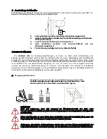
Bewegung der Maschine 


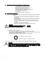
Die Maschine kann mit Hub- oder Transportmitteln bewegt werden. 

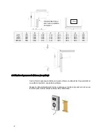
DIE 

FIXIERSCHRAUBEN ABSCHRAUBEN, UM DAS UNTERGESTELL DER 
VERPACKUNG VON DER EINHEIT ABZUNEHMEN 

(fig. A). 


HINWEISE 

Sehr gut aufpassen, dass sich niemand im Manövrierbereich des Hub-  oder 

Transportmittels aufhält, um w ährend der Bew egung der Ladung jegliche Unfallgefahr 

zu vermeiden. 


Wenn die Maschine in einer Kiste bzw . Holzkäfig verpackt verschickt w ird, muss die 

Verpackung für den Transport entsprechend verzurrt werden. 


Aufpassen, dass keine Schw ankungen durch eine zu hohe Hubgeschw indigkeit der 

verpackten Maschine verursacht werden, da die Maschine sonst herunter fallen könnte. 

Fig. A 

Summary of Contents for GM1

Page 1: ...GM TOUCH CONTROL I GB F D E MANUALE USO E MANUTENZIONE USE AND MAINTENANCE INSTRUCTIONS NOTICE DE MODE D EMPLOI ET D ENTRETIEN GEBRAUCHS UND WARTUNGSHANDBUCH MANUAL DE USO Y MANUTENCI N...

Page 2: ...alle fonti di energia 7 1 Allacciamento energia elettrica 7 2 Allacciamento impianto idraulico 8 Comandi elettrici 8 1 Pannello di comando e controllo 8 2 Icone display 9 Controlli regolazioni e regi...

Page 3: ...ore di informarsi presso il costruttore circa le eventuali controindicazioni o pericoli derivanti da uso improprio della macchina La macchina deve essere impiegata in conformit alle istruzioni di impi...

Page 4: ...rma Cavo luce cella Cavo micro porta Cavo resistenza porta Modello Model ZANOTTI S p A ViaMartin L King nr 30 46020 PEGOGNAGA Mantova Italy Modello Model Matricola Serial Number Tensione Voltage Assor...

Page 5: ...scambiatore termico condensatore Il compressore frigorifero di tipo ermetico a moto alternativo alimentato dalla rete elettrica monofase o trifase Lo sbrinamento per iniezione di gas caldo standard o...

Page 6: ...un funzionamento ottimale dell unit si consiglia di A Posizionare la macchina in ambiente con un buon ricambio d aria e lontana da elevate fonti di calore B Aprire la cella il minimo indispensabile C...

Page 7: ...d il foro praticato sulla parete utilizzando il raccordo nel quale stata preventivamente infilata la resistenza di scarico solo per modelli Bassa temperatura Bloccare poi il raccordo con la vite in do...

Page 8: ...110 400 440 590 100 GM340 830 364 410 110 522 440 590 100 6 6 Fissaggio del pannello remoto optional Fissare il fondo del pannello remoto alla parete prescelta utilizzando i fori esistenti avendo cura...

Page 9: ...e con viti Il costruttore ha predisposto le seguenti protezioni elettriche a Protezione termica ventilatori incorporati nei motori a reinserzione automatica protezione degli elettroventilatori da asso...

Page 10: ...la arresto della macchina esclusione allarme temperatura per circa un ora dopo la chiusura della porta L unit dotata del cavo necessario a tale collegamento e segue questa logica contatto microinterru...

Page 11: ...na circolazione dell acqua deve essere di almeno 1 bar 8 Comandi elettrici 8 1 Pannello di comando econtrollo SET Premere e rilasciare Visualizza e modifica il setpoint Conferma i comandi PRG Premere...

Page 12: ...issa luce cella accesa Off altrimenti NON USATA NON USATA NON USATA NON USATA NOTE All accensione lo strumento esegue un Lamp Test per qualche secondo il display e i leds lampeggiano a verifica dell i...

Page 13: ...ario mantenerla in questo stato per almeno tre ore Se la macchina prevede il monitor di tensione necessario mantenerla in OFF per almeno 7 minuti affinch il monitor effettuila fase diconteggio Regolar...

Page 14: ...izzare getto d aria soffiando dall interno verso l esterno Qualora non fosse possibile utilizzare un getto d aria eseguire con un pennello a setola lunga sull esterno del condensatore Nel caso di cond...

Page 15: ...l uso di strumenti metallici taglienti appuntiti o l utilizzo di acqua calda 3 In caso di mancata accensione del display della centralina verificare la presenza di tensione il corretto collegamento d...

Page 16: ...rico prodotto in cella troppo caldo Malfunzionamento impianto frigorifero Bassa temperatura AL1 Si attiva il led rosso di allarme ed il relativo rel nella sezione allarmi compare AL1 Malfunzionamento...

Page 17: ...di alimentazione subisce delle variazioni superiori a 12 si ha l intervento del dispositivo In questo caso si attiva il led rosso ed il led di allarme Nella sezione allarmi si potr visualizzare EA La...

Page 18: ...nformit alle leggi vigenti nel Paese in cui viene utilizzato l apparecchio 15 SMALTIMENTO DELLA MACCHINA In caso di rottamazione i componenti della macchina non devo essere dispersi nell ambiente ma d...

Page 19: ...the unit 7 1 Electric connection 7 2 Connection to water system 8 Electric controls 8 1 Control panel 8 2 Icons display 9 Checks regulations andadjustments 9 1 Starting 10 Wiring 11 Maintenance and re...

Page 20: ...about the possible dangers and contra indications connected with an improper use of the machine The unit shall be used following these instructions and sticking to the destination of use indicated by...

Page 21: ...Room light cable Microdoor cable Modello Model ZANOTTI S p A Via Martin L King nr 30 46020 PEGOGNAGA Mantova Italy Modello Model Matricola Serial Number Tensione Voltage Assorbimento Marcia Run Absor...

Page 22: ...22 Door heater cable...

Page 23: ...is brought again into the liquid state by mechanical compression at a higher pressure followed by cooling in another heat exchanger condenser The compressor is hermetic with reciprocating motion supp...

Page 24: ...ddischarge D Fit a drain line to the defrost water drain connection in the lower part of the unit Note GM units are equipped with automatic evaporation of defrost water drain is just a precaution in c...

Page 25: ...h the appropriate screw Fill the hole in the wall with insulating material polyurethane or silicone and mount the hole cover E C E D B F A A mm B mm C mm D mm E mm F a GM1 19 316 288 83 43 6 GM2 19 31...

Page 26: ...ecting cable between panel and unit making sure not to bundle it with other cables ATTENTION Maximum distance between panel and unit is 10 mt For longer distances the special long distance module shou...

Page 27: ...8 Cleaning Clean the unit carefully Remove any dust foreign substances and dirt possibly deposited during handling Use detergents and degreasers ATTENTION Solvents are not allowed 7 Connecting the un...

Page 28: ...following microswitch closed door closed ATTENTION Above microswitch is not supplied with the unit If the microdoor cable is disconnected or damaged the same conditions will occur as in case of open d...

Page 29: ...correct operation of the unit 8 Electric controls 8 1 Control panel SET Press and release Display and modify the Setpoint Confirms commands PRG Press and release Displays any alarms if active Opens Ma...

Page 30: ...the room light is ON Off otherwise NOT USED NOT USED NOT USED NOT USED NOTES When the controller is powered on it performs a lamp test during which time the display and LEDs will Flash for several sec...

Page 31: ...cold room temperature Press ON OFF key for 5 seconds to switch the uniton ATTENTION Medium temperature range 10 5 C Low temperature range 15 25 C Setting room temperature Connect the unit to the main...

Page 32: ...if necessary replace them 12 2 Serviceoperationstobecarried out by qualifiedtechniciansor by themanufacturer Following operations shall be carried out by qualified technicians or by the manufacturer...

Page 33: ...ned many times a day WARNING Removal of protections during machine operation is absolutely forbidden They have been developed to safeguard the operator s safety 12 4 Alarms When an alarm condition occ...

Page 34: ...e unit is turned off automatically The alarm relay is activated nPA is displayed in the alarm menu To reset the unit turn it off and then on again Faulty operation of condenser fan Dirty condenser Swi...

Page 35: ...d of according to the regulations in force in the country where the unit is used 15 HOW TO DISPOSE OF THE UNIT Do not discharge scrapped components in the environment They should be disposed of by com...

Page 36: ...rcesd nergie 7 1 Branchement nergie lectrique 7 2 Branchement installation hydraulique 8 Commandes lectriques 8 1 Panneau de commande et de contr le 8 2 Ic ne Afficheur 9 Contr les et r glages effectu...

Page 37: ...du constructeur en ce qui concerne d ventuelles contre indications ou dangers provoqu s par un usage impropre de la machine La machine doit tre utilis e conform ment au mode d emploi et pour l usage...

Page 38: ...teur magn tothermique Jamais directement la ligne principale Sens de rotation Couleur fils c ble secteur Attention important nettoyer de temps en temps le condenseur avec un jet d air de l int rieur v...

Page 39: ...tre changeur thermique condenseur Le compresseur frigorifique est de type herm tique mouvement alternatif aliment par le r seau lectrique monophas ou triphas Le d givrage par injection de gaz chaud st...

Page 40: ...eillons de A Placer la machine dans une pi ce ayant un bon rechange d air et loign e de sources de forte chaleur B Ouvrir la chambre le moins possible C S assurer que l unit ait la possibilit d une bo...

Page 41: ...tilisant le raccord dans lequel on aura pr alablement enfil la r sistance d coulement seulement pour les mod les Basse temp rature Bloquer ensuite le raccord avec la vis fournie Remplir le trou dans l...

Page 42: ...0 440 590 100 GM340 830 364 410 110 522 440 590 100 6 6 Fixation du panneau distance en option Fixer le fond du panneau distance la paroi choisie en utilisant les trous existants et en veillant mainte...

Page 43: ...charpente par des vis deblocage 2 Protections fixes externes lectroventilateurs sur l unit de condensation et d vaporation elles sont fix es par des vis Le constructeur a pr vu les protections lectri...

Page 44: ...b 230V 3 50 60 Hz Quatre fils Gris Jaune Vert Marron Noir Phase Terre Phase Phase c 400V 3 50 Hz Cinq filS Bleu Jaune Vert Marron Gris Noir Neutre Terre Phase Phase Phase Nous conseillons l installati...

Page 45: ...condensation est par eau et doit tre effectu en respectant les indications ENTREE et SORTIE eau situ es pr s des tubes auxquels il faut se brancher N oubliez pas que le diam tre des tubes utilis s po...

Page 46: ...en fonctionnement normal ON OFF Allumage permanent L unit est arret e Off l unit est allum e MENU COMPRESSEUR Allumage permanent locage modification param tres Allumage permanent compresseur fonction...

Page 47: ...courant L afficheur s allume et pr sente l indication OFF Si la machine pr voit le pr chauffage il faut maintenir la machine dans cet tat pendant au moins trois heures Si la machine pr voit le monite...

Page 48: ...es aux mains utiliser des gants de protection AVERTISSEMENT Avant d intervenir sur la machine couper le courant 12 1 Entretien extraordinaire Contr lez de temps en temps l tat d usure des contacts lec...

Page 49: ...ses techniques et ne pas avoir trouv d anomalies dans l installation il faut v rifier l tanch it des portes de la chambre froide qu il n y ait pas de d perditions de froid dans la chambre que la chamb...

Page 50: ...branch e non correctement Remplacement sonde Sonde condensation E3 Le voyant rouge et le relais d alarme s activent L afficheur affiche l inscription E3 altern e la temp rature interne de la chambre a...

Page 51: ...utomatiquement Avertissement Lors du premier allumage le moniteur effectue un comptage d environ 7 minutes Il est important que la machine soit gard e sous tension mais en conditions de OFF pendant to...

Page 52: ...tre mis au rebut suivant les lois en vigueur dans le Pays o la machine est utilis e 15 MISEAU REBUTDE LA MACHINE En cas de mise la ferraille les composants de la machine ne doivent pas tre abandonn s...

Page 53: ...an das Stromnetz 7 2 Anschluss an die hydraulische Anlage 8 Elektrische Steuerungen 8 1 Steuer und Kontrollschalttafel 8 2 Display Symbole 9 Durchzuf hrende Kontrollen Einstellungen und Registrierung...

Page 54: ...er Nutzung der Maschine ergeben Die Maschine muss entsprechend den Einsatzanleitungen und f r den vom Hersteller vorgesehenen Gebrauch verwendet werden Jeder nicht korrekte Einsatz der Maschine stellt...

Page 55: ...r verbinden Nie an die Hauptlinie anschlie en Drehrichtung Farben der Versorgungskabel Achtung wichtig Den Kondensator regelm ig mit Luftstrahl von innen nach au en reinigen Eingriff bei nicht laufend...

Page 56: ...anderen W rmeaustauscher Kondensator Der K hlkompressor ist hermetischer Art mit abwechselnder Bewegung und wird von einem Ein oder Dreiphasen Stromnetz versorgt Die Enteisung mittels Einspritzung von...

Page 57: ...rden A Das Ger t an einem gut bel fteten Ort und von W rmequellenentfernt aufstellen B Die Zelle m glichst wenig ffnen C Versichern Sie sich dass das Ger t gen gend Luft aufnehmen kann und auch ber ei...

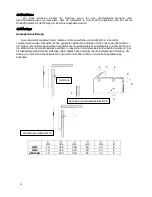
Page 58: ...uben befestigen Dann bringen Sie das Ger t an der Zelle an die Verbindung zwischen dem Ablass der Tauwasserschale des Verdampfers und dem Bohrloch in der Wand mit dem Verbindungsst ck ausf hren in das...

Page 59: ...g des Stopfens C D E G A B C D E F G H GM1 735 264 280 110 400 335 375 100 GM2 830 264 280 110 400 335 590 100 GM3 830 364 350 110 400 440 590 100 GM340 830 364 410 110 522 440 590 100 6 6 Befestigung...

Page 60: ...er auf der Kondensierungs und Verdampfereinheit mit Schrauben befestigt Der Hersteller hat folgende elektrische Schutzvorrichtungen vorgesehen a Automatisch funktionierende W rmeschutzvorrichtungen Ge...

Page 61: ...halten desGer ts Temperaturalarm aus bis etwa eine Stunde nach dem Schlie en der T r Das Aggregat verf gt bereits ber ein Kabel f r diesen Anschluss wobei die folgende Bedingung einzuhalten ist Mikros...

Page 62: ...1 Steuer undKontrollschalttafel SET Dr cken und loslassen Um den Sollwert zu visualisieren und ndern Um die Einstellung zu best tigen PRG Dr cken und loslassen Um eventuelle Alarme zu visualisieren f...

Page 63: ...altet Off Einwandfreier Maschinenbetrieb NICHT T TIG NICHT T TIG NICHT T TIG NICHT T TIG NOTE Beim Einschalten f hrt das Gerat einen Lichttest durch das Display und die LEDs leuchten f r einige Sekund...

Page 64: ...echnungsphase durchf hrt Den Set point der Zellentemperatur einstellen Die Maschine durch Bet tigung der ON OFF Taste in Betrieb nehmen ACHTUNG Einstellungsbereich Durchschnittstemperatur 10 5 C Einst...

Page 65: ...handschuhe tragen HINWEIS Vor Eingriffen an der Maschine die Spannung abstellen 12 1 Au erordentliche Wartung Regelm ig den Verschlei zustand der elektrischen Kontakte und Fernschalter berpr fen und w...

Page 66: ...nktionieren 4 Wenn das Display eingeschaltet ist und das Ger t bei Dr cken der ON OFF Taste nicht l uft muss berpr ft werden ob der T rmikroschalter richtig angeschlossen ist Dabei ist zu beachten das...

Page 67: ...wieder angezeigt wird ALARM DISPLAY URSACHE L SUNG Hochtemperaturalarm AH1 Die LED rot und das Alarmrelais sind aktiviert Die Anzeige des Alarmcodes HI erfolgt wenn man in die Alarmebene kommt wie be...

Page 68: ...r nicht verunreinigt ist Spannung von der K hlgruppe nehmen einige Minuten warten und Spannung einschalten Spannungsmonitor Alarm EA Der Monitor ist eine elektronische Vorrichtung mit der die Stromspa...

Page 69: ...men werden 14 ENTSORGUNG DER VERPACKUNG Verpackungen aus Holz Kunststoff Polystyrol m ssen gem den geltenden nationalen Gesetzen des Landes entsorgt werden in dem die Maschine eingesetzt wird 15 ENTSO...

Page 70: ...s fuentes externas de energ a 7 1 Conexi n energ a el ctrica 7 2 Conexi n sistema hidr ulico 8 Mandos el ctricos 8 1 Panel de mandos y control 8 2 Simbolos pantalla 9 Controles ajustes y revisiones ar...

Page 71: ...s del Fabricante sobre eventuales contraindicaciones o peligros que se podr an deber a un uso improprio de dicho equipo El equipo debe utilizarse conforme a las instrucciones de uso y para los usos p...

Page 72: ...etot rmico Nunca directamente a la l nea principal Sentido de la rotaci n Colores de los hilos del cable de alimentaci n Cuidado importante limpie peri dicamente el condensador con chorro de aire desd...

Page 73: ...73 Cable resistencia puerta...

Page 74: ...tercambiador t rmico condensador El compresor frigor fico es de tipo herm tico con movimiento alternativo y est alimentado por la red el ctrica monof sica o trif sica El descarche por inyecci n de gas...

Page 75: ...e A Coloque el equipo en un entorno que disponga de un buen cambio de aire y lejos de fuentes excesivas de calor B Abra la c mara lo m nimo indispensable C Cerci rese de que el equipo cuenta con una b...

Page 76: ...nillos apropiados A continuaci n coloque el equipo en la c mara realice la conexi n entre el desag e de la bandeja de evaporaci n y el agujero realizado en la pared utilizando el racor en que habr int...

Page 77: ...a en todo el per metro del tamp n C D E G A B C D E F G H GM1 735 264 280 110 400 335 375 100 GM2 830 264 280 110 400 335 590 100 GM3 830 364 350 110 400 440 590 100 GM340 830 364 410 110 522 440 590...

Page 78: ...ra y evaporadora est n sujetados contornillos El Fabricante ha predispuesto las siguientes protecciones el ctricas a Protecci n t rmica ventiladores incorporados en los motores de reinserci n autom ti...

Page 79: ...i n de la alarma de la temperatura durante una hora aprox tras el cierre de la puerta El equipo viene dotado del cable necesario para dicha conexi n y sigue la siguiente l gica contacto micro interrup...

Page 80: ...ue ser por lo menos de 1 bar 8 Mandos el ctricos 8 1 Panel demandosy control SET Pulsar y soltar Visualiza y modifica el setpoint Confirmar el valor PRG Pulsar y soltar Visualiza alarmas eventuales si...

Page 81: ...menti LUZ NO UTILIZADA Encendida fija Luz c mara encendida Off Luz c mara apagada NO UTILIZADA NO UTILIZADA NO UTILIZADA NO UTILIZADA NOTE Al encendido el instrumento realiza una prueba Lamp Test dura...

Page 82: ...dicho monitor realice la fase de c mputo Regule el set point de la temperatura de la c mara Ponga en marcha el equipo pulsando por 5 segundos la teclaON OFF CUIDADO Campo regulaci n media temperatura...

Page 83: ...SO Antes de manipular el equipo quite la corriente 12 1 Manutenci n extraordinaria Compruebe peri dicamente el estado de desgaste de los contactos el ctricos y de los telerruptores y si es necesario c...

Page 84: ...t conectado que la conexi n del cable de alimentaci n sea correcta los fusibles del cuadro el ctrico 4 Si la pantalla se enciende y al pulsar la tecla ON OFF el equipo no se pone en marcha compruebe q...

Page 85: ...ecci n de alarmas come se indica m s arriba Excesivas aperturas de la puerta Carga excesiva de producto en la c mara Carga de producto demasiado caliente en la c mara Malfuncionamiento del sistema fri...

Page 86: ...la secci n de las alarmas aparecer EA El equipo sigue parado durante unos 6 minutos tras los cuales si las condiciones lo permiten vuelve a ponerse en marcha autom ticamente Aviso la primera vez que s...

Page 87: ...los componentes del equipo no han de abandonarse en el medio ambiente han de ser eliminados a trav s de empresas autorizadas a la recogida y a la recuperaci n de desechos especiales conforme a las le...

Page 88: ...TENZA CARTER COMPRESSORE M1 COMPRESSOR CRANKCASE HEATER RESISTANCE CARTER COMPRESSEUR KOMP LSUMPFHEIZUNG RESISTENCIA DEL CARTER DEL COMPRESOR RESIST NCIA DO CARTER COMPRESSOR M1 EP RESISTENZA PORTA DO...

Page 89: ...COMPRESSOR M1 K11 TELERUTTORE SBRINAMENTO DEFROST CONTACTOR TELERUPTEUR DEGIVRAGE ABTAUFERNSCHALTER CONTACTOR DESCARCHE INTERRUPTOR DE DEGELO M1 MOTORE COMPRESSORE n 1 COMPRESSOR MOTOR Nr 1 MOTEUR COM...

Page 90: ...TILATORGESCHW REGLER AUS INTERR EXCLUSION VARIADOR VELOCIDAD VENT COND INTERRUPTOR DESLIGA VAR VELOCIDADE T TRASFORMATORE TRANSFORMER TRANSFORMATEUR TRANSFORMATOR TRANSFORMADOR TRASFORMADOR X MORSETTI...

Page 91: ...1 490 36 BGM11202F R404A 3922 0 34 1 333 48 BGM11702F R404A 3922 0 35 1 372 70 BGM21802F R404A 3922 0 86 3 372 92 BGM22002F R404A 3922 0 84 3 294 48 BGM32002F R404A 3922 0 96 3 765 12 BGM33002F R404A...

Page 92: ......

Page 93: ......

Page 94: ...Zanotti S p A Via M L King 30 46020 Pegognaga MN Italy Tel 0376 5551 Fax 0376 536554 Info zanotti com www zanotti com 0MAN106 M 10 2016...

Reviews: