13
Mod. CINEA CANALIZÁVEL
rev 00
Installation
translated from the original text
IT
IT
FR
FR
ES
ES
NL
NL
EN
EN
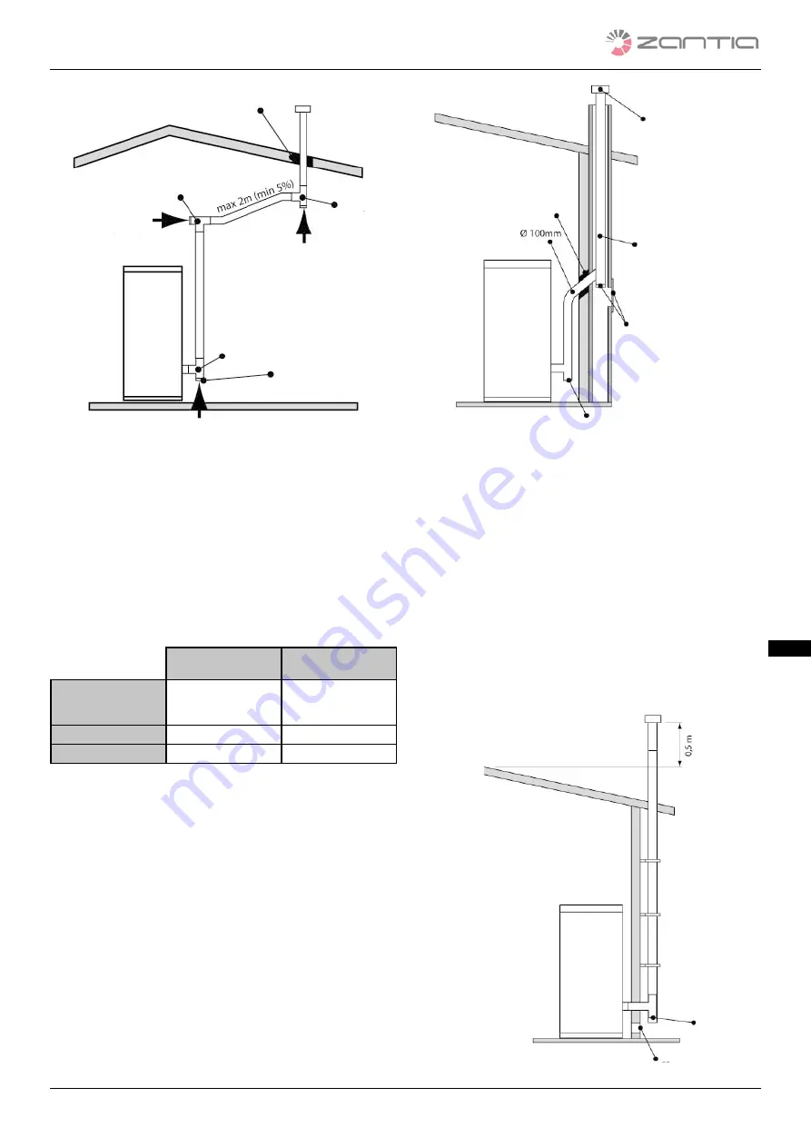
fig. 8 pipe length
2.5.7
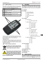
BORES FOR PASSAGE OF EXHAUST PIPE
ON WALL OR ROOF: RECOMMENDED IN-
STALLATION AND DIAMETER
Once the position of the stove has been established (par.
2.5.6), a hole must be drilled for passage of the flue gas ex-
haust pipe. This varies according to the type of installation
(and of the exhaust pipe diameter) and on the type of wall or
roof. The insulation material must have mineral origin (rock-
wool, ceramic fibre) with a nominal density exceeding 80 kg/
m3.
Insulation thickness
[mm]
Diameter of the
holes [mm]
Wooden wall, or
anyway flammable or
with flammable pa ts
100
300
Cement wall or roof
50
200
Brick wall or roof
30
160
tab.4 bore diameter for exhaust pipe passage
2.5.8
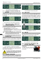
USING A TRADITIONAL FLUE
If you wish to use an existing flue, we recommend having
it checked by a professional chimney sweep to ensure that
it is fully airtight. This is because the flue gas, being slightly
pressurised, can infiltrate into possible cracks in the flue and
invade the living areas. Should the flue not result in perfect
conditions after the inspection, it is advisable to have it sealed
with new materials. In the event of a large-size existing flue,
we recommend inserting a pipe having a diameter of maxi-
mum 150 mm; it is also advisable to insulate the flue gas ex-
haust pipe. The following figures describe the solutions to be
chosen in the event an existing flue is used
Insulation
Tee fitting
Tee fitting
Airtight cap
Tee fitting
Cleaning
direction
Cleaning
direction
Cleaning direction
.
fig. 9 traditional flue
2.5.9
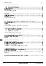
USING AN EXTERNAL FLUE GAS DUCT
AN external flue gas duct can be used only if it meets the fol-
lowing requirements:
• Only insulated (double-walled) stainless steel pipes must
be used fastened to the building (following fig.).
• An inspection must be provided at the base of the duct
to carry out periodic verifications and maintenance oper-
ations.
• It must have a wind barrier chimney and respect the "d" dis-
tance from the ridge of the building as shown in par. 2.4.3, tab.
1.
• The following figure shows the solution to be chosen in the
event an external fuel gas duct is used.
Chimney
Insulation
Inspection
doors
Max Ø 150
Tee fitting
Inspection
Air intake with non-lockable grille


