background image


A. GENERAL INFORMATION 


a.1 

General safety rules 


ATTENTION PLEASE!!! You can never be too cautious: before the installation read and 
comply with these fundamental Rules:   


All  local  regulations,  including  those  referring  to  national  and  European  laws,  must  be  respected  while  installing  the 

stove.  


Verify  if  the  electrical  system  and  the  mains  outlets  are  able  to  bear  the  maximum  absorption  of  the  stove,  which  is 

reported  on  the  plate.  Connect  the  stove  to  a  norm-compliant,  230v  –  50Hz  mains  outlet.    Avoid  using  adapters, 

multiple  sockets  or  extensions.  Make  sure  the  electrical  system  is  provided  with  a  norm-compliant  earthing  and 

differential switch.  


In order to install the stove you must respect the current laws regarding the exhausting through the flue. It is advisable 

to connect the stove to the flue by a terminal, which should be easy to inspect. We remind you that it is necessary to 

refer  to  an  authorized  assistance  center  for  the  installation  and  periodical  maintenance  of  the  stove,  so  to  check  the 

efficiency of the flue draught, before and after the combustion work of the stove.  


While  seasonally  using the stove,  in case  of  bad  draught  of  unfavorable  weather conditions  (temperature  lesser  than 

0°C), verify if the flue is perfectly cohibented and not obstructed, so to avoid its freezing and the danger of a reflux.  


In case of fire inside the flue, immediately switch the stove off.   


The stove consumes as much air as it is necessary for the combustion; it is thus advisable to connect the stove to the 

outside by a suitable piping, ending at the special slot on the back of the stove.  


Given the weight of the stove, before the installation, make sure the pavement is able to bear it.  


If  the  pavement  is  made  of  inflammable  material,  such  as  parquet  or  carpeting,  position  a  plate  under  the  stove  to 

protect it, (consider that, on the front of the stove, the plate should exceed the stove by at least 25/30cm).   


For your safety, it is advisable to maintain a distance of at least 20cm between the hot sides of the stove and possibly 

inflammable covering materials (such as glass-beaded walls, wallpapers et cetera); otherwise, to use specific insulating 

materials, available on sale. Please make this consideration also regarding the furniture, armchairs, curtains and so on.   


In order to facilitate the possible interventions by the technical assistance, do not fit the stove inside closed spaces and 

do not place it adjacent to the walls, for this may compromise the correct afflux of the air.   


The lack of draught by the flue (or, for instance, the obstruction or closing of the air entrance of the grate, or of the grate 

itself)  alters  the  functioning  of  the  stove,  which,  while  automatically  switching-on,  may  provoke  an  excessive  pellet 

dosage in the grate, due to delayed fire priming. Excessive smoke in the combustion chamber can cause an automatic 

priming  of  the  fumes  (gas),  accompanied  by  a  violent  flame;  in  these  conditions,  we  recommend  never  opening  the 

combustion chamber door.    


Categorically avoid using inflammable liquids to start the fire; when the stove is on, the pellet lighting is automatic.   


The pellets feeding the stove must necessarily present the characteristics described in this handbook.  


Do not touch the glass when the stove reaches its temperature; be cautious before touching the stove.  


Avoid  letting  children  close  to  the  stove  on  their  own,  when  it  is  on,  because  each  hot  surface  can  provoke  severe 

burns.  


Do  not  perform  interventions  on  the  stove,  apart  from  those  expected  for  a  regular  functioning  or  suggested  in  this 

handbook  in  order  to  solve  slight  problems.  In  any  case,  always  unplug  the  stove  from  the  power  supply  before  an 

intervention, and operate solely when the stove is cold.  


It is absolutely forbidden to remove the guard protecting the pellet tank.  

5

Summary of Contents for HEBE

Page 1: ...PELLET STOVE HEBE OPERATING AND MAINTENANCE HANDBOOK...

Page 2: ......

Page 3: ...ou may know and use the product at its best as well as ordinarily upkeep it Our authorized technical service remains at Your complete disposal for any necessity Best regards ZANTIA PLEASE NOTE ZANTIA...

Page 4: ...temperature setpoint c 13 Stand by c 14 Turning off the stove c 15 The menu c 16 User menu c 17 Menu M1 SET CLOCK c 18 Menu M2 Set chrono c 19 Menu M3 Language selection c 20 Menu M4 Stand by c 21 Men...

Page 5: ...the stove to protect it consider that on the front of the stove the plate should exceed the stove by at least 25 30cm For your safety it is advisable to maintain a distance of at least 20cm between t...

Page 6: ...fter fixing the problem at its origin ZANTIA is not responsible for inconveniences tampering breakages or any other damage due to non observance of the instructions reported in this handbook The handb...

Page 7: ...W Pellet tank capacity 13Kg Pellet consumption min 0 4Kg h Pellet consumption max 1 4Kg h Digital control display YES Week program YES Room thermostat YES Manual automatic functioning YES Adjustable f...

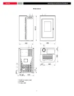
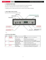
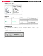
Page 8: ...Dimensions 1 Switch and power socket 2 Air intake 3 Fumes outlet 8...

Page 9: ...n the installation and test are performed by an authorized ZANTIA assistance center We would like to make clear that the guarantee expires in case of tampering breakages and similar due to non observa...

Page 10: ...s when used in the same room or space of the device b 2 Moving and transporting Make sure that the devised used for lifting and transporting the stove support its weight which is reported on the ident...

Page 11: ...ed FIG 2 INSTALLATION WITH AN EXISTING FLUE Flue gas outlet 80 Reach the existing flue horizontally making sure that it presents a minimum section of 200cm and an easy to inspect base for its annual c...

Page 12: ...mains outlets present the capacity to support the maximum absorption of the stove which is reported on the plate Make sure the system is provided with a norm compliant earthing and differential switch...

Page 13: ...g 2 c 2 The use of the buttons button Description mode action P1 Decrease temperature TEMPERATURE SETPOINT Decreases the value of the room temperature SETPOINT PROGRAMMING Decreases the selected param...

Page 14: ...status c 4 Display Display Function Conditions Displayed info DISPLAY Power status parameter name OFF OFF ROOM TEMPERATURE IGN IGNITION ROOM TEMPERATURE FEED PELLET FEED OPERATING ROOM TEMPERATURE OP...

Page 15: ...LED ON During the second phase after the period of time set in the PR40 parameter has elapsed the auger turns off the auger LED turns off for the period of time set in the PR41 parameter The speed of...

Page 16: ...is phase after the period of time set in the PR03 parameter the stove cleans the brazier The message Clean brazier scrolls on the display the auger remains ON auger LED ON and runs at the speed set in...

Page 17: ...g power is automatically brought to the minimum In this case the message Modulate appears on the display figure 10 If the room temperature drops below the set value temperature setpoint the stove retu...

Page 18: ...e room temperature drops below the set temperature room setpoint minus the threshold set in the PR43 parameter the stove re starts c 14 Turning off the stove To turn off the stove simply press and hol...

Page 19: ...M2 2 daily programming 01 day chrono on off 02 start 1 day OFF 0 23 50 03 stop 1 day OFF 0 23 50 04 start 2 day OFF 0 23 50 05 stop 2 day OFF 0 23 50 M2 3 weekly programming 01 weekly chrono on off 0...

Page 20: ...chrono end week on off 02 start end week 1 OFF 0 23 50 03 stop end week 1 OFF 0 23 50 04 start end week 2 OFF 0 23 50 05 stop end week 2 OFF 0 23 50 M2 5 exit set M3 select language 01 Italian set 02...

Page 21: ...or 2 seconds Press P1 decrease or P2 increase to select M1 The message M1 set clock scrolls across the display figure 13a Fig 13a Fig 13b Select the required day and press P3 figure 13b Next using the...

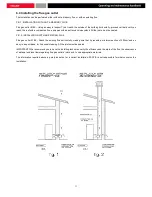
Page 22: ...Fig 13f Fig 13 22...

Page 23: ...nstructs the clock to ignore the command Press P1 decrease and P2 increase to make changes and press P3 to confirm DAILY PROGRAM Menu level selection meaning possible values M2 2 01 CHRONO DAY Enables...

Page 24: ...lection meaning possible values M2 3 11 START PRG 2 activation time OFF 0 23 50 M2 3 12 STOP PRG 2 deactivation time OFF 0 23 50 M2 3 13 MONDAY PRG 2 reference day on off M2 3 14 TUESDAY PRG 2 on off...

Page 25: ...d and press P1 decrease or P2 increase to set ON Setting the Start 1 weekend and Stop 1 weekend times sets the period of operation for Saturday while setting the Start 2 weekend and Stop 2 weekend set...

Page 26: ...progress figure 17 Press P1 or P2 to enable or disable the buzzer and press P3 to confirm c 22 Menu M6 Initial feeding This function is available only when the stove is OFF and allows feeding of the a...

Page 27: ...aning 3 1 Status of the pellet feeding auger 52 Time out Toff Thermostat status 106 Smoke temperature 1490 Smoke extraction speed c 24 Menu M8 Technical calibrations This menu option is reserved for t...

Page 28: ...ons d 5 General switch This electronic component of the stove is composed by a 4A fuse and by an electronic filter that protect the stove from electrical overload and electromagnetic inconveniencies d...

Page 29: ...of the stove Remove the furnace s internal covering accurately clean and remove the incrustations inside the crucible and its space Clean the fans and check the mechanism of the plays and of the fixi...

Page 30: ...for several seconds When an alarm is reset the stove turns off for a while in the interest of safety In the event of an alarm the alarm LED stays on alarm LED ON and the buzzer if enabled sounds inte...

Page 31: ...e display Fig 24 f 5 Failed start up alarm This occurs in the event of failed start up phase This alarm is triggered when the temperature of the smoke does not exceed the value of the PR13 parameter w...

Page 32: ...sage Al 7 alar al 7 Thermal Prot figure 27 appears on the display and the stove turns off Fig 27 f 8 No negative pressure alarm This alarm is triggered when the external pressure switch detects pressu...

Page 33: ...pellets in the tank Auger without pellets Fill the tank and proceed as indicated for the first lighting of the stove The stove is blocked for an unsuccessful pellet supply Technical problem with the...

Page 34: ...34...

Page 35: ...35...

Page 36: ...ARANTEE CONDITIONS AT THE END OF EACH SEASON IT IS OBLIGATORY TO HAVE THE AUTHORIZED ASSISTANCE CENTER PERFORM A GENERAL CLEANING OF THE THERMO STOVE OTHERWISE THE GUARANTEE WILL EXPIRE HEBE 00 100320...

Reviews: