49
Mod. NARA PL. 15-20 rev 01
Instructions for use
translated from the original text
IT
IT
FR
FR
ES
ES
EN
EN
IT
IT
FR
FR
ES
ES
EN
EN
4.2
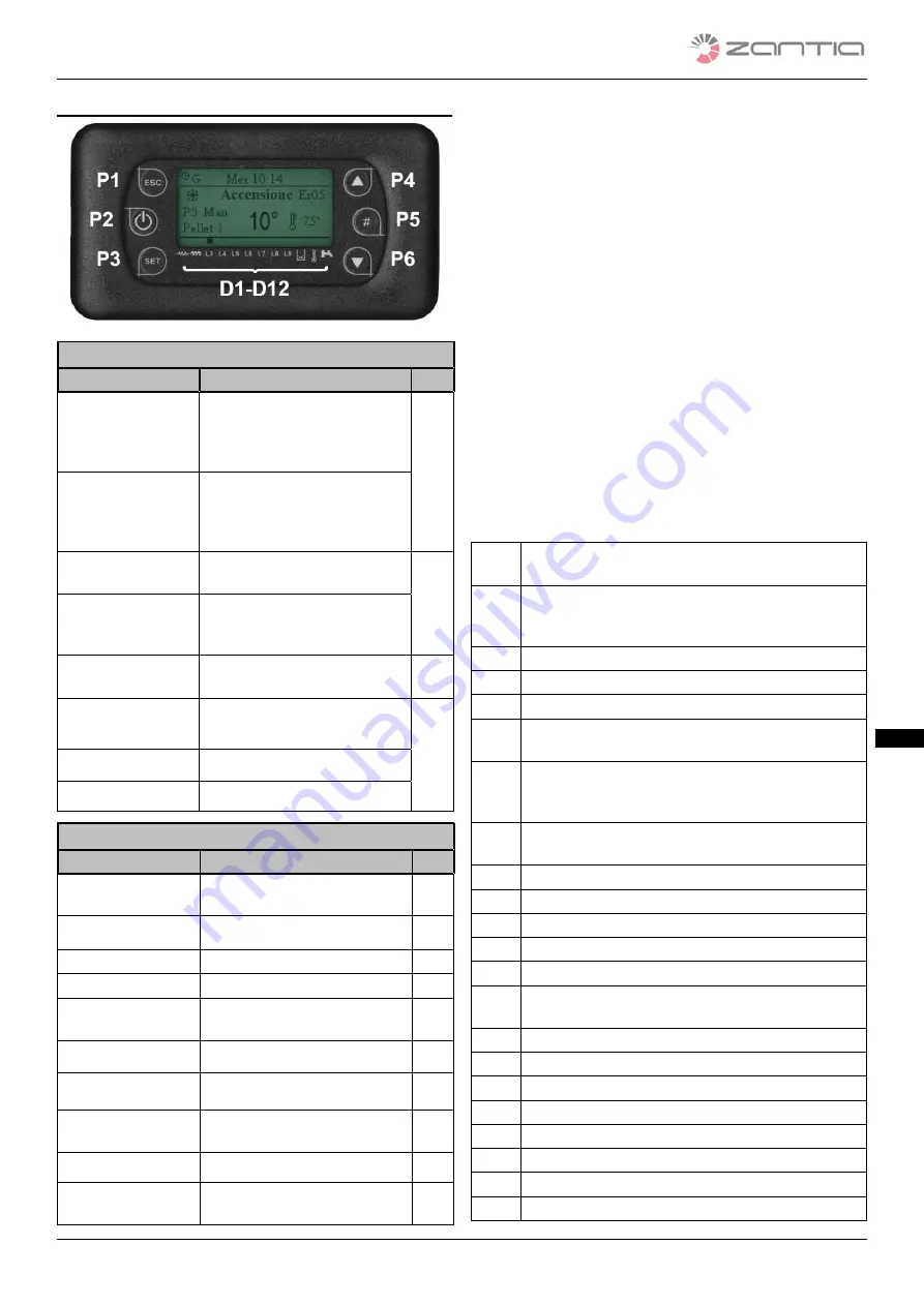
LCD CONTROL PANEL
Keys
Function
Description
Key
On/Off
Switch On and Off
by pressing
and holding the key for 3 se-
conds until the acoustic signal
sounds
P2
Unlock
Unlock
the system by pressing
and holding the key for 3 se-
conds until the acoustic signal
sounds
Modify Data Value
Menu
From the Menu,
the data va-
lues can be modified
P4
P6
Menu and Sub-
menu Scrolling
From the Menu,
the Menus
and Sub-menus can be scrol-
led
Esc
Function to
exit a Menu or
Sub-menu
P1
Menu
Function to
enter a Menu or
Sub-menu
P3
Modify
Enter modify in Menus
Set
Save data in Menus
Led
Function
Description
Key
Glow plug
LED On: Glow plug on
D1
Auger
LED On: Auger in ON interval
D2
Pump
LED On: Pump active
D3
Valve
LED On: Valve active
D4
V2 Output
LED ON: V2 output active
D5
Aux2 output
LED On: Aux2 output active
D6
Aux3 output
LED On: Aux3 output active
D7
Pellet Level
LED On: the sensor indicates a
lack of material
D10
Chronothermostat
LED On: Open contact
D11
Flow switch
LED On: domestic water requi-
red (closed contact)
D12
Display
-Main screen::
-Data displayed on the main screen:
Local and remote control panel
Date and time, chrono mode activation (daily, weekly,
weekend), power, automatic/manual combustion, summer/
winter mode, system operation status, error code detected.
Local control panel
Both the set and current temperatures are referred to the
boiler.
Remote control panel
Both the set and current temperatures are referred to the en-
vironment.
-Operational statuses displayed:
Check-up, switch-on, stabilisation, modulation, stand-by,
normal, safety, switch-off, restart, lock, switch-off.
4.2.1
ERROR MESSAGES
Messages, such as those indicating an error, may be displayed
on the main control panel screen.
All errors lock the system.
Er01
High voltage Safety Error 1. It may even intervene
when the system is switched off.
Er02
High voltage Safety Error 2. It can only intervene
when the Combustion Fan is active. It indicates an
incorrect or insufficient draught.
Er03
Switch-off due to low-temperature smoke
Er04
Switch-off due to water overtemperature
Er05
Switch-off due to elevated smoke temperature
Er07 Encoder error.
This error occurs when
there is no
Encoder signal
Er08
Encoder error. This error occurs when there is a re-
gulation problem regarding the number of revolu-
tions.
Er11
Clock Error. This error occurs when there is a pro-
blem with the internal clock.
Er12
Switch-off due to Failed Start-up
Er15
Switch-off due to lack of power
Er16
RS485 communication error
Er17
Air Flow Regulation Failed
Er18
Out of Pellets
Er23
Boiler Probe, Return Boiler Probe or Puffer Probe
open
Er25
Brazier Cleaning Motor broken
Er26
Cleaning Motor broken
Er27
Cleaning Motor 2 broken
Er34
Depression under minimum treshold
Er35
Depression over maximum treshold
Er39
Flow Meter Sensor broken
Er41
Minimum air flow not reached during Check-Up
Er42
Maximum air flow exceeded
Summary of Contents for NARA PLUS 15
Page 2: ......
Page 32: ......
Page 62: ......
Page 67: ......
Page 68: ...Mod NARA PLUS 15 20 rev 01...


