


25
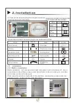
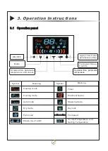
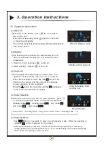
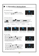
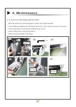
3. Operation Instr uctions
Serial Number
12-15
10-13
8-12
10-15
8-12
5-10
4-8
0
(
OFF
),
1
(
ON
)
0
(
OFF
),
1
(
ON
)
14
1 2
1 0
1 2
1 0
7
5
1
0
1
2
3
4
5
6
7
8
9
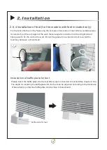
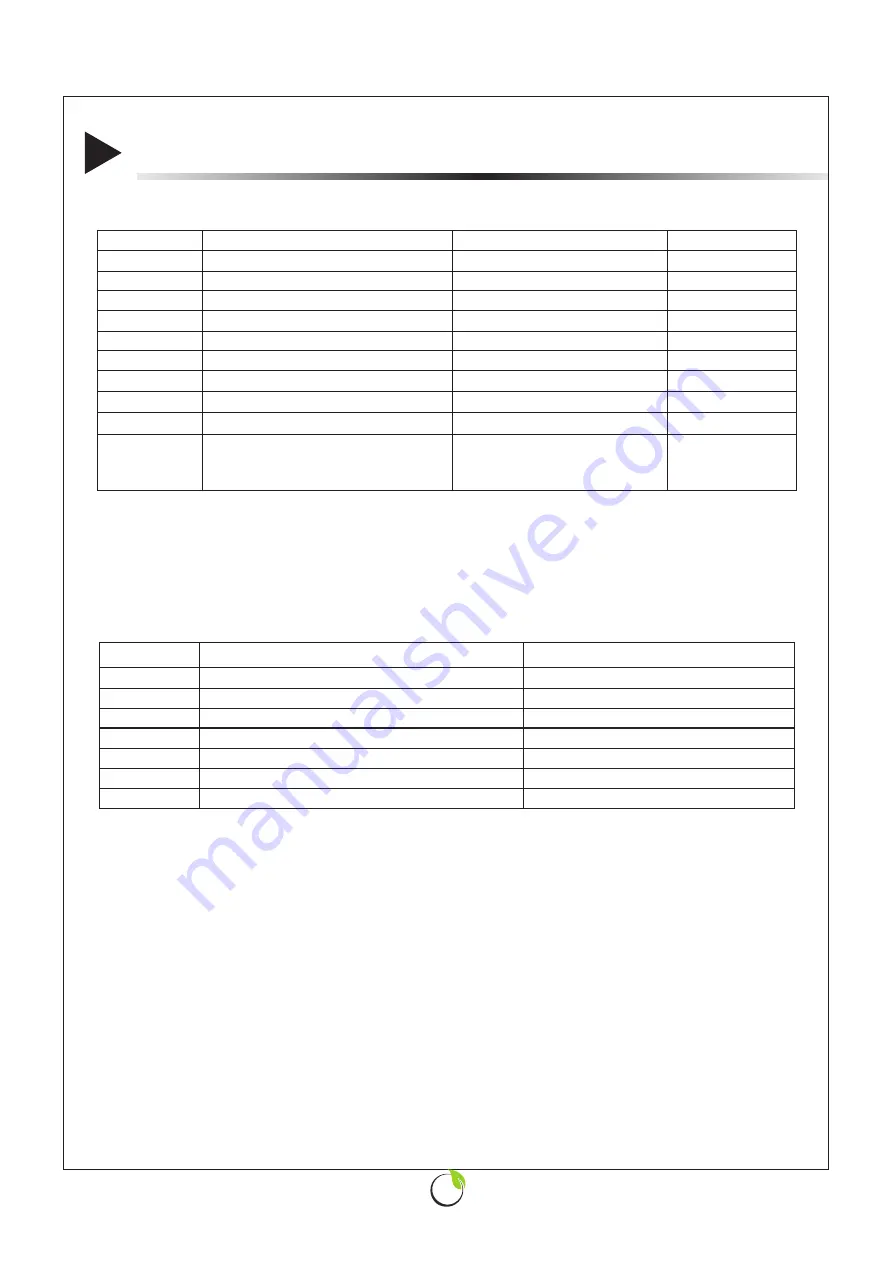
Possible causes
Error Code Displayed
Air inlet temperature sensor failure
Water inlet temperature sensor failure
DC motor failure
Wired controller temperature sensor failure
Wired controller humidity sensor failure
Bottom wired controller communication failure
485 wired controller communication failure
E
1
E
2
E
3
E
4(
parameter 9 valid
)
E
5(
parameter 9 valid
)
E
6
E
7(
parameter 9 valid
)
1
2
3
4
5
6
7
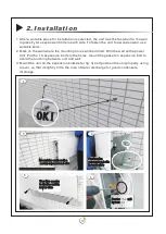
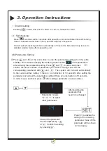
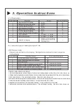
(11) Parameters
Meaning
Range
Default Setting
High fan speed of cooling
Medium fan speed of cooling
Low fan speed of cooling
High fan speed of heating
Medium fan speed of heating
Low fan speed of heating
Super low fan speed of heating
Valve functions
485 communication
Ps
:
Actual fan speed = Setting fan speed * 100
(12) Failure
code
Failure code will flash on the display
.
Multiple failure code will come in sequence
on the display
Serial Number
Failure code shows up when:
1. Air inlet temperature sensor failure: Cancel room temperature control, the error code
shows
up
.
2. Water inlet temperature sensor failure: Cancel water inlet temperature limit, the error code shows
.
3. DC motor failure
:
The unit stops running, the error code
shows
up
.
4. Wired controller temperature sensor failure
:
Cancel room temperature control, the error code
shows
.
5. Wired controller humidity sensor failure
:
It only shows the error code.
6. Bottom wired controller communication failure
:
It only shows the error code.
7. 485 wired controller communication failure
:
The unit stops running, the error code
shows
up
.
10
ON/OFF of display
0(OFF in 5min without
operation of unit is off),
1(always on)
1
Summary of Contents for SLIM-C Series
Page 2: ......
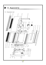
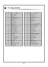
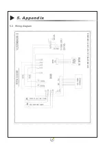
Page 34: ...31 5 Appendix 5 1 Exploded view...
Page 36: ...33 5 2 Wiring diagram 5 Appendix...
Page 38: ...NOTES...
Page 39: ......
Page 40: ...www ZAN TIA com...


