background image

10

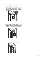
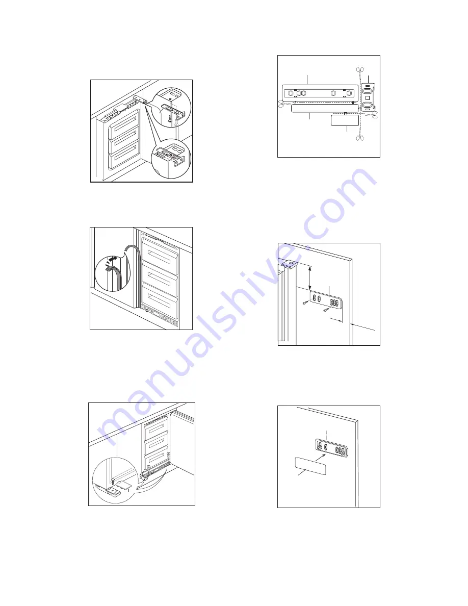
3. Apply joint the sealing strip as shown in figure.

D478

2. Push the appliance against the side opposite the

door hinge. The appliance is fitted with 2 brackets
(C) for securing it to the side of the kitchen unit; fit
these as shown in the figure.

D476

B

C

A

4. Secure the appliance to the base with the 2

screws supplied. Fit hinge cover (D), clipping it
into place.

D

5. Separate parts A, B, C, D as shown in the figure.

PR266

A

B

C

D

6. Place guide (A) on the inside part of the furniture

door, up and down as shown in the figure and
mark the position of external holes. After having
drilled holes, fix the guide with the screws
supplied.

20mm

A

50mm

PR166

7. Fix cover (C) on guide (A) until it clips into place.

P R 3 3 / 2

C

A

Summary of Contents for CI100FB

Page 1: ...INSTRUCTION BOOKLET ËÁ  ÁÈ ÙËÓ ÙÔ Ôı ÙËÛË Î È ÙË Ú ÛË FREEZER æÀ 2222738 59 t z CI 100 FB ...

Page 2: ...he If the power plug socket is loose do not insert the power plug Damage to the cord may cause a short circuit fire and or electric shock Do not use electrical appliances inside the appliance Do not keep carbonated drinks or bottles in the freezer compartment The glass bottles may break Ice lollies can cause Ôfrost freezer burnsÕ if consumed straight from the freezer It is dangerous to try and alt...

Page 3: ...move the typical smell of a brand new product then dry thoroughly Do not use detergents or abrasive powders as these will damage the finish Remove safety elements used for transportation Safety Instructions 2 Disposal 2 Use and Control Before Use 3 Control panel Starting the appliance Temperature control 4 NORMAL SUPER switch and quick freezing Warning light Freezer calendar 4 Interior accessories...

Page 4: ...d Frequency with which the door is opened and how long it is left open the location of the appliance The temperature inside the appliance is automatically adjusted Setting ã1Ò hightest temperature warmest setting Setting ã6Ò lowest temperature coldest setting A medium setting is generally the most suitable Warning light red If the temperature warning light 4 lights up it indicates that the tempera...

Page 5: ...zen food to touch food which is already frozen thus avoiding a rise in temperature of the latter Do not touch frozen food with wet hands Your hands could stick to the food and cause skin abrasions It is advisable to show the freezing in date on each individual pack to enable you to keep tab of the storage time Be sure that frozen foodstuffs are transferred from the foodstore to the freezer in the ...

Page 6: ...ried out Prooceed as follows Remove any stored food wrap it in several layers of newspaper and put it in a cool place Pull out the plug from the wall socket or turn the ON OFF switch 2 to position ÇOÈ Leave the door open and introduce the plastic scraper in the appropriate seating at the base of the cabinet as shown in the figure and place a basin underneath to collect the defrost water see fig D0...

Page 7: ...ve normal room temperature Check that the ventilation is sufficient and that the ventilation openings are unobstructed The cause could be the introduction of large quantities of food and or frequent opening closing of the door Sometimes this is normal Temperature control may cause clicking sounds when the system is connected or disconnected The injected cooling gas may produce a gurgling sound whi...

Page 8: ...e classification SN 10 to 32 C 16 to 32 C 18 to 38 C 18 to 43 C N ST T for an ambient temperature of 50 mm min 200cm2 200 cm 2 min D526 When the ambient temperature is not included within the range indicated for the class of this appliance the storage temperature in the appliance cannot be guaranteed therefore it is advisable to use the food stored as soon as possible Electrical connection Before ...

Page 9: ...art involved with a normal hairdrier D163 B A Dimensions of the recess Height of housing 1 702 mm Depth of housing 2 550 mm Width of housing 3 560 mm It is necessary that the niche is provided with a conduct of ventilation having the following dimensions Depth 50 mm Width 540 mm PR0 540 50 3 2 1 Building in To ensure adequate ventilation follow the instructions in the figure The appliance door mus...

Page 10: ...B C A 4 Secure the appliance to the base with the 2 screws supplied Fit hinge cover D clipping it into place D 5 Separate parts A B C D as shown in the figure PR266 A B C D 6 Place guide A on the inside part of the furniture door up and down as shown in the figure and mark the position of external holes After having drilled holes fix the guide with the screws supplied 20mm A 50mm PR166 7 Fix cover...

Page 11: ...uares and drill holes with 2 mm at 8 mm from the outer edge of the door Place the small square on the guide again and fix it with the screws supplied 8mm PR167 A B 9 Should the lining up of the furniture door be necessary use the clearance of slots At the end of operations it is necessary to check if the door of the furniture closes properly PR168 10 Fix cover D on guide B until it clips into plac...

Page 12: ......

Reviews: