


14
Instructions for the installer
The following instructions are meant for a qualified
installer, in order that the operations of installation,
regulation, and service are executed according to the
existing regulations.
Before using the unit, take off the special protective layer
which protects the stainless steel and anodyzed tin
parts. Whenever changes are mode involving the
disconnection of the machine it is necessary to proceed
with maximum caution.
Positioning and levelling
In order to function normally it is imperative that this unit
is installed in a well ventilated kitchen (regarding the
installation follow the existing regulations). The appliance
is of freestanding type and must be installed according
to the existing regulations.
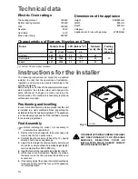
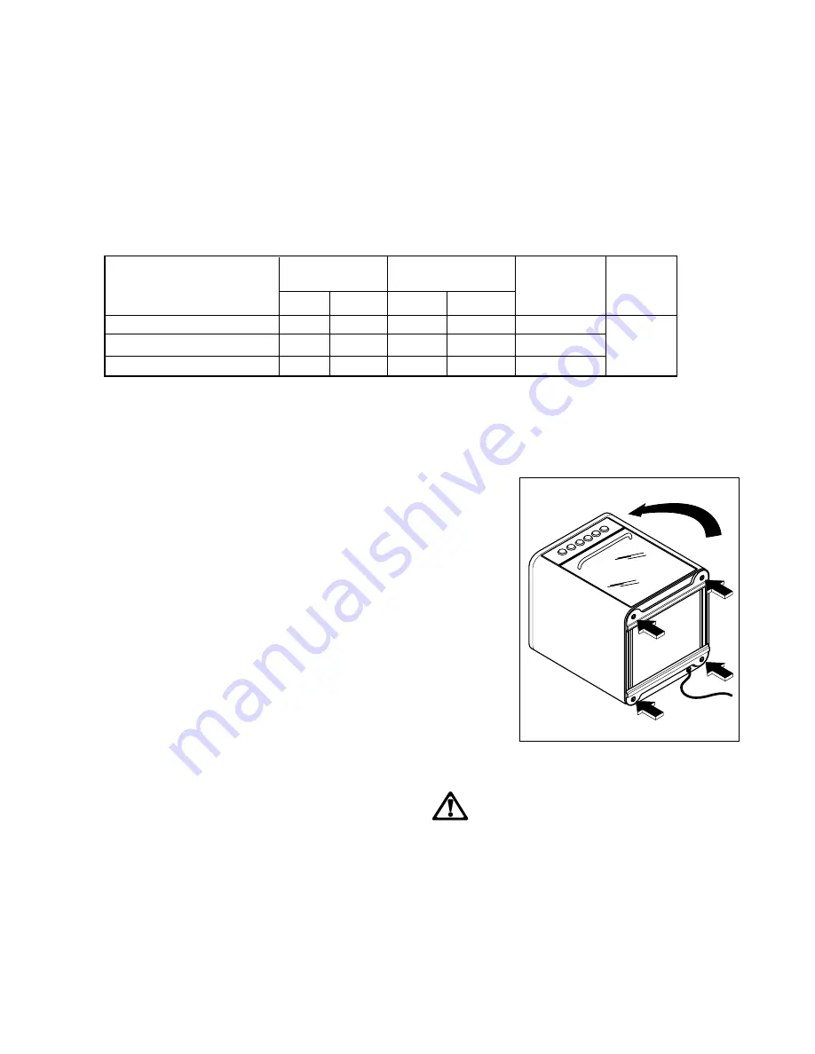
Feet Assembly
Before installing the cooker, it is necessary to
assemble the supplied feet.
1.
Remove the hob pan supports, the burner caps and
crowns and the oven accessories.
2.
Carefully lean the cooker on its back (Fig. 15), paying
attention not to cause any damage.
3.
Adjust the feet height by unscrewing the bottom part
of each foot, until you obtain the required height (height
can be adjusted from 850 to 880 mm).
4.
Insert the feet into the relevant holes indicated in fig.15.
5.
Lift the cooker in vertical position. Replace the crowns,
the burner caps, the hob pan supports and the oven
accessories.
6.
If necessary, adjust the cooker horizontal levelling by
turning the bottom part of the feet, until the appliance
is completely stable.
Electric Oven ratings
Top heating element
1000 W
Bottom heating element
1200 W
Grill
1800 W
Oven fan
30 W
Oven lamp
15 W
Max. power rating:
2250 W
Technical data
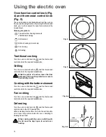
Dimensions of the appliance
Height
850/880 mm
Width
600 mm
Depth
600 mm
Category:
I3
Appliance set for use with gas type:
LPG30mbar
Characteristics of Burners, Nozzles and Taps
F
Fig. 15
FO 2283
THE MANUFACTURING COMPANY DECLINES
ANY RESPONSABILITY FOR POSSIBLE
DAMAGES RESULTING FROM AN
INSTALLATION WHICH DOESN'T COMPLY
WITH THE RULES IN FORCE
Burner
Nominal Power LPG (Butane "A")
Diameter
Feeding
Tap. By-Pass Pressure
kW
kCal/h
Nozzle
g/h
mbar (*)
Auxiliary
0,95
814
50
75
28
Semi-rapid
1,60
1368
65
126
35
30
Rapid
2,45
2095
80
193
45
(*) 1 mbar = 10 mm. water coloumn.


