


6
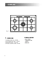
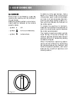
3 - USE OF COOKING HOB
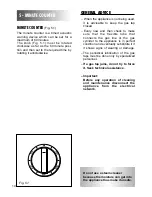
Fig. 3.1
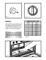
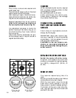
GAS BURNERS
Each burner is controlled by a gas tap
assuring the opening and the closing of
the gas supply.
Make the symbols printed on the knob to
match with the indicator on the control
panel to obtain:
– symbol
●
: off
– symbol
: full on (nominal rate)
– symbol
: reduced rate
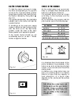
To light one of the gas burners, hold a
flame (i.e. a match) close to the top part
of the burner, push in and turn the relati-
ve knob in an anti-clockwise direction,
pointing the large flame symbol (i.e.
max. gas flow) towards the indicator on
the control panel.
To reduce the gas flow to minimum,
rotate the knob further anti-clockwise to
point the small flame symbol towards
the control panel indicator.
The maximum aperture position permits
rapid boiling of liquids, whereas the
minimum aperture position allows slower
warming of food or maintaining boiling
conditions of liquids.
Other intermediate operating adjust-
ments can be achieved by positioning
the indicator between the maximum and
minimum aperture positions, and never
between the maximum aperture and
closed positions.