background image

4

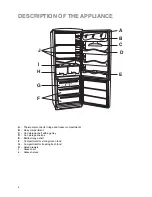
DESCRIPTION OF THE APPLIANCE

A

B

C

 D

E

F

G

H

I

J

FAST FREEZE

12

9

6

A

-  Thermostat control for fridge and freezer compartments

B

- Dairy 

compartment

- Can storage shelf with egg tray

-  Can storage shelves

-  Bottle storage shelf

-  Compartment for storing frozen food

G -

Compartment for freezing fresh food 

- Salad 

drawers

- Glass 

shelf 

- Glass 

shelves 

17

INSTALLATION

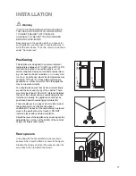
Positioning

This appliance is designed to operate in ambient

temperatures between 10¡C (50¡F) and 32¡C (90¡F).

It should be located in a dry atmosphere, out of

direct sunlight and away from extreme temperature

e.g. not next to a boiler or radiator, or in a very cold

room e.g. an outhouse, where the temperatures may

fall below 10¡C (50¡F). If these temperatures are

exceeded i.e. colder or warmer, then the appliance

may not operate correctly.
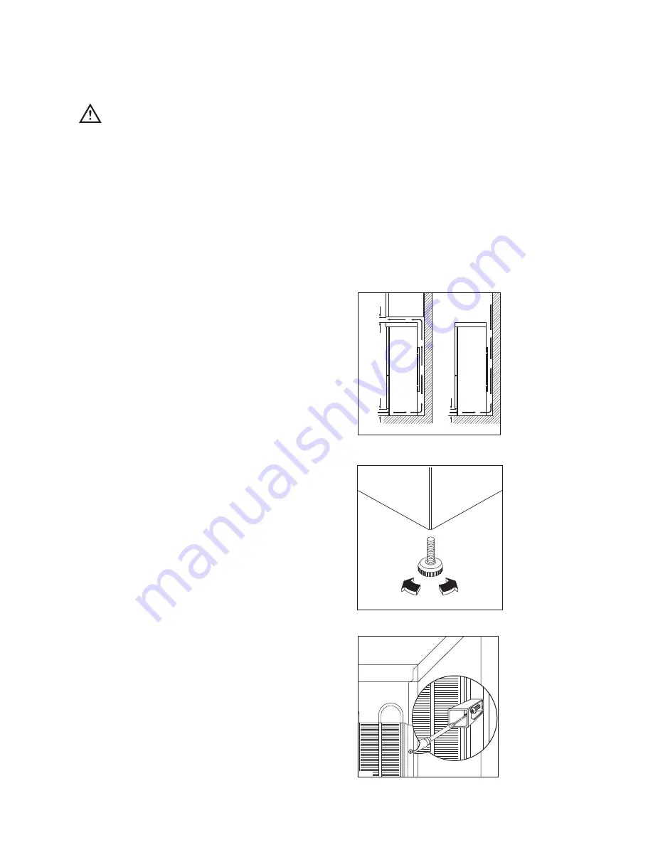
You should also ensure that air can circulate freely

around the back and the top of the cabinet. There

must also be at least 100 mm (4Ó) distance between

the top of the cabinet and any overhanging kitchen

furniture (A). Ideally, the appliance should not be

positioned beneath overhanging furniture (B).
There should also be a gap of 25 mm either side of

the appliance. Do not obstruct the space

underneath. The back of the cabinet may be placed

close to the wall but must not touch it. DO NOT

install in places with restricted ventilation.
Adjust the level of the appliance by screwing out the

adjustable foot, or feet, at the bottom of the cabinet

using your fingers (see figure).

D200

PR153

NP002

100 mm

10 mm

10 mm

A

B

Warning

IF YOU ARE DISCARDING AN OLD APPLIANCE

THAT HAS A LOCK OR CATCH ON THE DOOR,

YOU MUST ENSURE THAT IT IS MADE

UNUSABLE TO PREVENT YOUNG CHILDREN

BEING TRAPPED INSIDE.
Depending upon the position which you choose for

your appliance, you may wish to reverse the way in

which the door opens. To do this, refer to instructions

under ÒDoor reversalÓ.

Rear spacers

In the bag with the documentation, there are two

spacers which must be fitted as shown in the figure.
Slacken the screws and insert the spacer under the

screw head, then re-tighten the screws.

Summary of Contents for ZA 34 S

Page 1: ...REFRIGERATOR FREEZER ZA 34 S INSTRUCTION BOOKLET 2222 116 42 ...

Page 2: ...amages to the cooling unit with consequent possible fluid leakages The appliance must not be located close to cookers radiators or boilers Avoid prolonged exposure of the appliance to direct sunlight Do not use other electrical appliances such as ice cream makers inside of refrigerating appliances During Use This appliance is designed for domestic use only specifically for the storage of edible fo...

Page 3: ...on 6 Movable shelves 7 Positioning the door shelves 7 Meat box 7 Hints and Tips 8 Maintenance and Cleaning 9 Internal cleaning 9 External cleaning 9 When the appliance is not in use 9 Changing the light bulb 9 Defrosting 9 Something Not Working 11 Service and Spare Parts 12 Customer Care 12 Guarantee Conditions 15 Instructions for the Installer Technical Specification 16 Installation 17 Positionin...

Page 4: ...hermostat control for fridge and freezer compartments B Dairy compartment C Can storage shelf with egg tray D Can storage shelves E Bottle storage shelf F Compartment for storing frozen food G Compartment for freezing fresh food H Salad drawers I Glass shelf J Glass shelves ...

Page 5: ...ppliance is working efficiently when the room temperature drops below 16 C the switch mounted next to the thermostat control should be switched on No damage can be caused by leaving the switch in this position for any period of time see page 11 Low ambient operation However should the temperature rise above 16 C remember to turn the switch off again The freezer compartment The four star freezer co...

Page 6: ...the refrigerator compartment and small pieces of meat can even be cooked while still frozen but you must ensure that it is thoroughly cooked through Vegetables should be directly immersed in boiling water ready cooked dishes can be placed directly in the oven in their aluminium wrapping A microwave oven is particularly suitable for thawing any type of frozen or deep frozen food follow the oven ins...

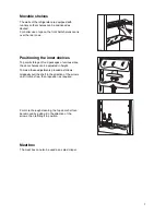
Page 7: ...storage of food packages of various sizes the door shelves can be adjusted in height To make these adjustments proceed as follows Gradually pull the shelf in the direction of the arrows until it comes free then reposition as required For more thorough cleaning the top door shelf can be removed by pulling it in the direction of the arrows then refitting it in position Meat box The meat box can also...

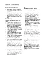
Page 8: ... of frozen goods The numbers indicate storage times in months for the appropriate types of frozen goods Whether the upper or lower value of the indicated storage time is valid depends on the quality of the foods and pre treating before freezing Energy Saving Advice Do not install the appliance close to sources of heat such as a boiler or radiator Locate the appliance in a cool well ventilated room...

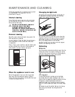
Page 9: ... the appliance with a brush or vacuum cleaner see figure D273 CONDENSER COMPRESSOR DEFROST TRAY Before any maintenance or cleaning work is carried out DISCONNECT the appliance from the ELECTRICITY supply Internal cleaning Clean the inside and accessories with warm water and bicarbonate of soda 5ml to 0 5 litre of water Rinse and dry thoroughly NEVER USE DETERGENTS ABRASIVE POWDERS HIGHLY PERFUMED ...

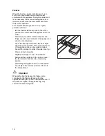
Page 10: ...d store in a cool dry place Leave the door open and insert the ice scraper under the channel in the centre of the lower part of the appliance place a low sided container beneath the scraper to collect the water see fig Clean and dry thoroughly Replace the scraper in one of the drawers Reconnect the appliance to the mains or reset the thermostat control knob to a functioning position After letting ...

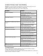
Page 11: ...s power at the socket Check there is not a power cut by checking the household lights Check the fuse has not blown Ensure that the bulb is correctly fitted Replace the bulb if it has blown Check the door light switch is not jammed Check the thermostat control knob in the fridge is turned to the correct setting relative to ambient conditions Check the ambient temperature is within the applianceÕs o...

Page 12: ...hase date For general enquiries concerning your Zanussi appliance or for further information on Zanussi products please contact our Customer Care Department by letter or telephone at the address below or visit our website at www zanussi co uk Customer Care Department Zanussi 55 77 High Street Slough Berkshire SL1 1DZ Tel 08705 727 727 calls to this number may be recorded for training purposes Duri...

Page 13: ...13 ...

Page 14: ...14 ...

Page 15: ...lls to put right an appliance which is improperly installed or calls to appliances outside the European Community EC or European Free Trade Area Appliances found to be in use within a commercial environment plus those which are subject to rental agreements Products of Zanussi manufacture which are not marketed by Zanussi European Guarantee If you should move to another country within Europe then y...

Page 16: ... Hz TOTAL POWER ABSORBED 100 W AVERAGE DAILY UNITS ELECTRICITY 0 90 kWh GROSS CAPACITY Fridge 222 l Freezer 88 l NET CAPACITY Fridge 216 l Freezer 77 l This figure is based on standard test results in accordance with European Standard EN 153 Actual consumption will depend on how the appliance is used and where it is located ...

Page 17: ...uld also be a gap of 25 mm either side of the appliance Do not obstruct the space underneath The back of the cabinet may be placed close to the wall but must not touch it DO NOT install in places with restricted ventilation Adjust the level of the appliance by screwing out the adjustable foot or feet at the bottom of the cabinet using your fingers see figure D200 PR153 NP002 100 mm 10 mm 10 mm A B...

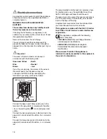
Page 18: ... which is marked with the letter ÇEÈ or the earth symbol or coloured green and yellow Connect the blue neutral wire to the terminal in the plug which is marked with the letter ÇNÈ or coloured black Connect the brown live wire to the terminal in the plug which is marked with the letter ÇLÈ or coloured red D207 GREEN YELLOW 13 AMP FUSE BROWN CORD CLAMP BLUE 13 AMP The plug moulded onto the lead inco...

Page 19: ...ing the screws previously removed insert the hole cover G on the lower hinge Slide the hole cover F out of the ventilation grille D by pushing it in the direction of the arrow and reassemble it on the opposite side 14 Refit the ventilation grill D to the base of the cabinet 15 On the side where the handle is to be fitted push in the blanking cover caps to free the new holes Remove the handles and ...

Page 20: ... Electrolux Household Appliances Limited 2000 ...

Reviews: