background image

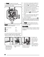
Warning! This appliance must be earthed.

The manufacturer declines any liability should these

safety measures not be observed.

1

2

3

4

5

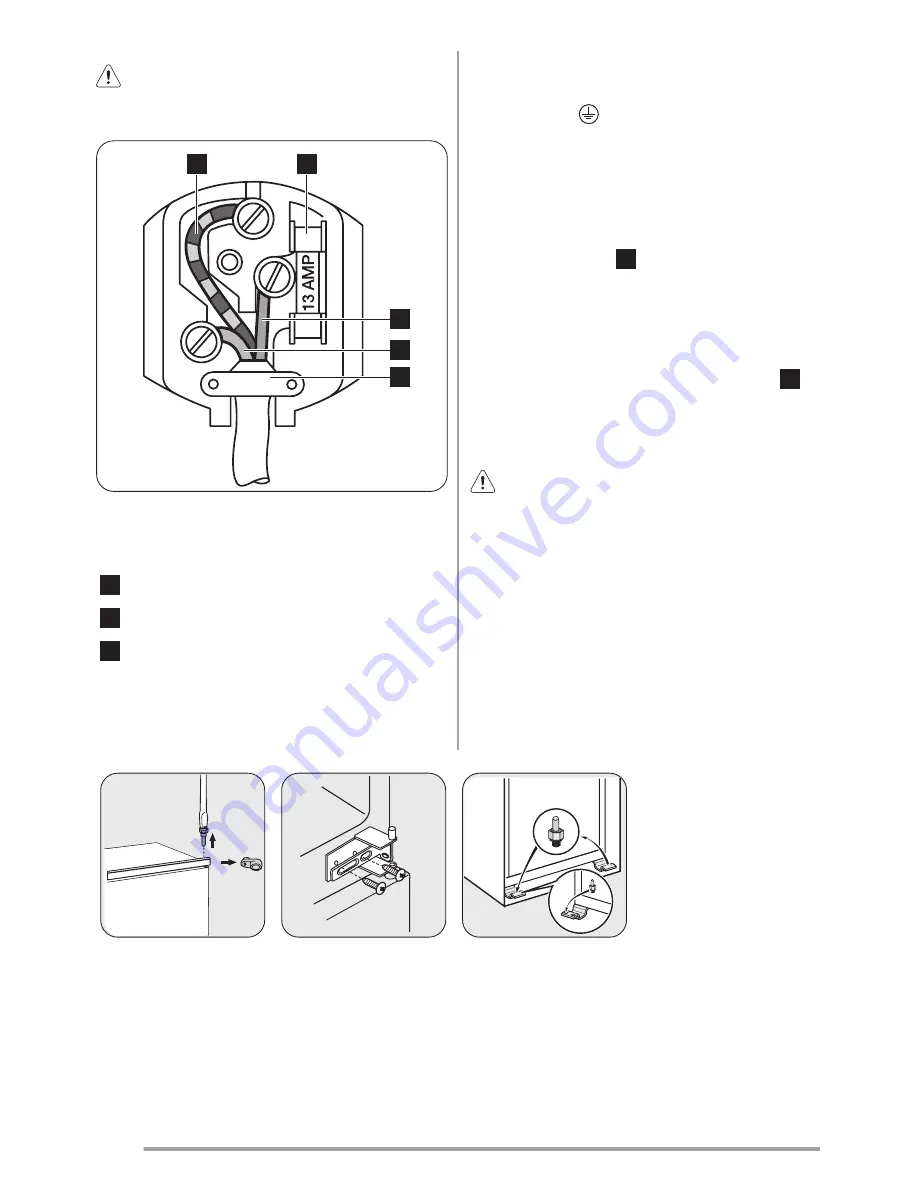
Important! The wires in the mains lead are coloured in

accordance with the following code:

1

Green and Yellow:

Earth

3

Brown:

Live

5

Blue:

Neutral

As the colours of the wires in the mains lead of this appli-

ance may not correspond with the coloured markings

identifying the terminals in your plug, proceed as follows:

1. Connect the wire coloured green and yellow to the

terminal marked either with the letter “E“ or by the
earth symbol   or coloured green and yellow.

2. Connect the wire coloured blue to the terminal either

marked with the letter “N“ or coloured black.

3. Connect the wire coloured brown to the terminal ei-

ther marked with the “L“ or coloured red.

4. Check that no cut, or stray strands of wire is present

and the cord clamp 

4

 is secure over the outer

sheath.

5. Make sure the electricity supply voltage is the same

as that indicated on the appliance rating plate.

6. Switch on the appliance.
The appliance is supplied with a 13 amp plug fitted 

2

 .

In the event of having to change the fuse in the plug sup-

plied, a 13 amp ASTA approved (BS 1362) fuse must be

used.

Warning! A cut off plug inserted into a 13 amp

socket is a serious safety (shock) hazard. Ensure

that it is disposed of safely.

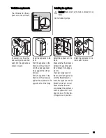
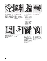
Door reversibility

The door of the appliance opens to the right. If you want to

open the door to the left, do these steps before you install

the appliance:

• Loosen the upper pin

and remove the spacer.

• Remove the upper pin

and the upper door.

• Loosen the middle

hinge.

• Remove the lower door.
• Loosen the lower pin.

On the opposite side:
• Install the lower pin.
• Install the lower door.
• Tighten the middle

hinge.

• Install the upper door.
• Tighten the spacer and

tighten the upper pin.

10


Summary of Contents for ZBB6284

Page 1: ...EN User manual Fridge Freezer ZBB6284...

Page 2: ...m children There is risk of suffocation If you are discarding the appliance pull the plug out of the socket cut the connection cable as close to the appliance as you can and remove the door to prevent...

Page 3: ...fore maintenance switch off the appliance and dis connect the mains plug from the mains socket Do not clean the appliance with metal objects Do not use sharp objects to remove frost from the ap plianc...

Page 4: ...appliance is set to the lowest temperatures it may run continuously causing frost to form on the rear wall In this case the dial must be set to a higher temperature to allow automatic defrosting and...

Page 5: ...storage of food packages of various sizes the door shelves can be placed at different heights Gradually pull the shelf in the direction of the arrows until it comes free then reposition as required H...

Page 6: ...iance you should make sure that the commercially frozen foodstuffs were adequately stored by the retailer be sure that frozen foodstuffs are transferred from the foodstore to the freezer in the shorte...

Page 7: ...bot tom centre placing a basin underneath to collect the de frost water In order to speed up the defrosting process place a pot of warm water in the freezer compartment In ad dition remove pieces of...

Page 8: ...Decrease the room temperature Water flows on the rear plate of the refrigerator During the automatic defrosting proc ess frost defrosts on the rear plate This is correct Water flows into the refriger...

Page 9: ...vice Center Technical data Dimension of the recess Height 1780 mm Width 560 mm Depth 550 mm Rising Time 18 h Voltage 230 240 V Frequency 50 Hz The technical information are situated in the rating plat...

Page 10: ...k that no cut or stray strands of wire is present and the cord clamp 4 is secure over the outer sheath 5 Make sure the electricity supply voltage is the same as that indicated on the appliance rating...

Page 11: ...the upper gap cover stops against the kitchen furniture Push the appliance in the direction of the arrows 2 against the cupboard on the opposite side of the hinge 44mm 4mm Adjust the appliance in the...

Page 12: ...ure sidewall 2 Tighten the screws of the part G again 3 Attach the part H to the part G Ha Hb Hc Hd Disconnect the parts Ha Hb Hc and Hd ca 50 mm ca 50 mm 21 mm 90 21 mm 90 Install the part Ha on the...

Page 13: ...emperature increases Environmental concerns The symbol on the product or on its packaging indicates that this product may not be treated as household waste Instead it should be taken to the appropriat...

Page 14: ...14...

Page 15: ...15...

Page 16: ...www zanussi com shop 222301064 A 472010...

Reviews: