5
INSTALLATION
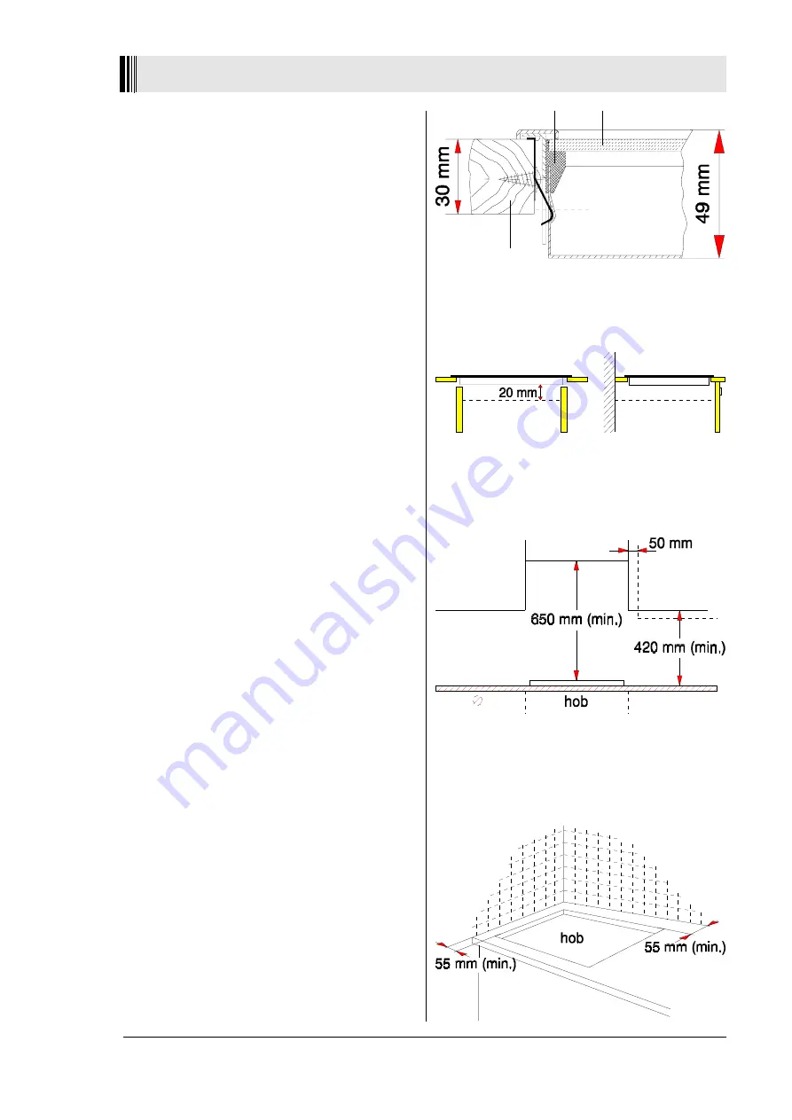
Fig.2
sealing
ceramic
worktop
When the cut out to the worktop is complete, lower the
hob into position to ensure that fits.
Remove the hob from the worktop and carry out the
electrical connection as described under the Electrical
Connection section.
Check that the foam seal along the underside of the
hob is fitted correctly.
Fix the spring clips with the enclosed screws on the
sides of the worktop inside the cut-out. The upper fold
on the clip-spring is there to fix the hob.
Position the springs in accordance to the enclosed
template.
Lower the hob into the opening and carefully press
first the rear, then the front side of the hob down until
it "snaps" into the springs.
The seal on the underside of the hob will ensure that it is
airtight between the hob and the work surface, this will
prevent any spillages from seeping into the cabinet
below. Place the hob carefully into the recess, with the
cable outlet of the hob at the back. Press firmly around
the edge of the hob, to compress the foam strip and
ensure an airtight seal.
Then, proceed to fix the hob firmly into the working
surface, with the 6 fixing clamps as shown in
Fig.2
,
making sure that the seal between the hob and the work
surface is secure by tightening the fixing clamps.
The distance between the underside of the hob and the
furniture beneath must be
at least 20 mm (Fig.3)
.
A minimum clearance height of
650 mm
is required
above a hob surface. Measure the lowest horizontal
surface of the hob to overhead cupboards ensuring there
is a minimum of
420 mm
between the hob surface and
underside of overhead cupboards is
(fig.4)
.
If the height between the worktop and the underside of the
overhead cupboards is less than
420 mm
a gap pf
50 mm
must be maintained either side of the hob up to a height
of
650 mm
(fig.4)
.
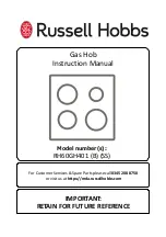
There must be a clearance of
55 mm
free of combustible
material to the side & back of the hob
(fig.5)
.
Important for the removal of the hob
1. Disconnect the appliance from the mains.
2. In order to take out the whole glassceramic hob, use
a medium flat screwdriver or spatula. Put it in between
the frame and worktop on the area where the snap-in
ressorts are located.
3. Then slightly lift the unit out. Take care not to damage
the worktop.
In terms of fire protection, the appliance conforms
to type Y (IEC 335-2-6). Only appliances of this type
may be installed on one side of adjacent upright
furniture housings or walls.
Fig. 5
Fig. 3
Fig. 4
All manuals and user guides at all-guides.com


