19
www.zanussi.com
• Install a multipolar switch that can
withstand the appliance load, with a
minimum opening between the contacts of
3 mm. Remember that the earth wire must
not be cut out by the switch.
Connecting the power cable
The all-electric cookers and some combi
versions are without supply cable and are
adjusted for single-phase power, butt they
can, with due modifications, be powered
by three phase systems by following these
instructions:
• Remove the rear panel from the cooker.
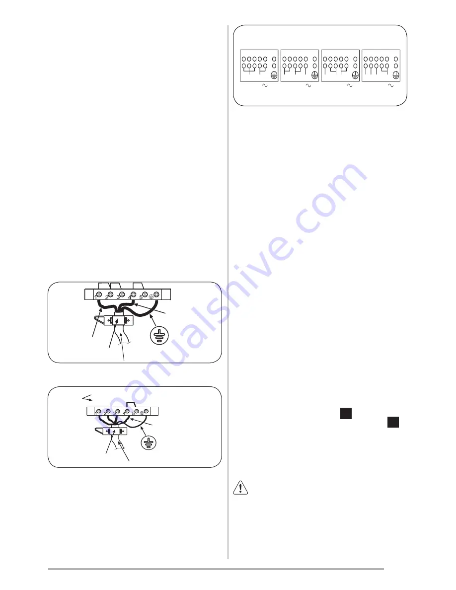
• Move the connecting plates in the terminal
board fig.7, following the diagram in fig. 8.
• You will also find this diagram affixed to the
back of the cooker.(fig.9) according to the
type of connection you want.
• Connect the power cable, whose cross
section must be suitable (see paragraph
«TECHNICAL FEATURES»), keeping the
earth wire longer than the phase wires.
• Secure the cable in the clamp and - fit the
rear panel in place.
fig.7
fig.8
fig.9
Adjustments
• Always disconnect the appliance from
the electricity supply before making
any adjustment.
• All seal must be replaced by the
technician following any adjustment
or regulation.
• The adjustment of the reduce rate
(simmer) must be undertaken only
with burners functioning on natural
gas while in the case of burners
functioning on L.P.G, the screw must
be locked down fully (in clockwise
direction).
• “Primary air adjustment” on hob gas
burners is unnecessary.
Taps
All gas taps are male cone type with only one
way of passage.
Adjustment of the
“Reduced rate”
position
as follows (fig.10):
• Turn the burner on and place the knob on
the “Reduced rate” position (small flame).
• Remove the knob of the tap which is
attached by simply applying pressure to the
rod.
• Insert a small screwdriver
1
into the
top shaft and turn the throttling screw
left or right until flame of the burner is
conveniently regulated to the low position.
• Check that the flame does not go out when
the knob is sharply switched from the “Full
on” to “Reduced rate” positions.
Attention!
This operation can be carried
out also with the front panel fitted, but
if you find some difficulties to reach the
adjustment screw, remove the front panel
unscrewing the fixing screws, which are
positioned in the inferior part of the same
and make to slip downwards.
2

