background image

20

www.zanussi.com

Gas information

To tighten some components apply the 

following torque forces: 

Aluminium pipes to burners, valves, 

thermostats: 15 Nm 

Thermocouples to top burners cups: 3 

Nm 

Thermocouples to thermostats: 4 Nm 

Push-on connector: 20 Nm 

Injectors: 4 Nm

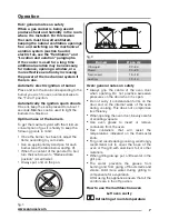
Fig. 10

Conversions

Replacing the injectors

Our burners can be adapted to different 

types of gas by simply installing the injectors 

suitable for the gas you want to use. 
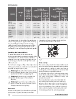
To change the injectors on the hob, remove 

the burner cup and head and with a 7 mm Ø 

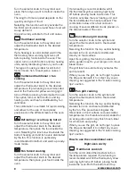
socket spanner replace them (fig. 11).
To help the installer, the table on in the


“Technical information” section.


gives the 

burner nominal heat input, injector diameter 

and operating pressure of the different gas 

types.

After having replaced the injectors, it 

will be necessary to proceed with burner 

adjustment as explained in the previous 

paragraphs. The technician must replace 

any seals after the adjustments have 

been made.

Fig. 11

Maintenance
Prior to any maintenance work or 

changing parts, disconnect the 

appliance from the gas and electricity 

power sources.

Replacing the taps

Proceed in the following way when replacing 

a tap or the thermostat:

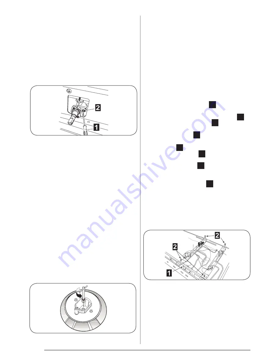
•  Remove pan supports, burner heads.

• Unscrew the burner fixing screws (four 

for ultrarapid burner and two for the other 

burners) 

•  Pull out the knobs. 

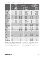
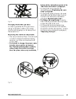
•  Unscrew the fixing screws

1

 (fig. 14) which 

lock the front panel to the front frame then 

slip out from the upper fixing brackets.

2


•  Unscrew the fixing screws 

1

(fig. 14 which 

lock the hob at the back and remove it.

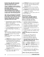
•  Unscrew the nuts 

2

of the gas aluminium 

pipes and pull out the thermocouple quick 

connectors 

3

(fig.13).

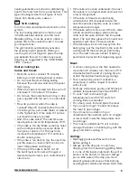
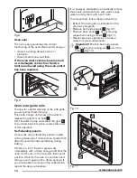
•  Unscrew the screws 

2

(fig. 12) which lock 

the crosspieces.l

•  Unscrew the screws 

1

(fig. 12) which unite 

the the bridles of the taps to the front frame.

•  Make to slip the ramp toward the back part 

and unscrew the screws 

1

(fig. 13) in order 

to free the taps.

•  Change seal each time a tap is replaced. 

This will ensure perfect retention between 

the tap and part.

•  Reassemble all the parts following the same 

procedure but in the reverse order.

Fig. 12

Summary of Contents for ZCK18307XA

Page 1: ...EN User Installation Manual Cooker ZCK18307XA ZCK98307XA ...

Page 2: ...in perfect condition If you have any doubts do not use the appliance and call in an authorised person The packaging materials used cardboard plastic bags polystyrene foam nails etc must not be left within easy reach of children because they are a potential hazard source All packaging materials used are environmentally friendly and recyclable The electrical safety of this appliance is only guarante...

Page 3: ...glass door since they can scratch the surface which may result in shattering of the glass Never use sponges or abrasive products and solvents to remove stains or adhesives on the painted or stainless steel surfaces Switch off the oven before removing the fan guard for cleaning Replace the guard after cleaning in accordance with the instructions The oven can be equipped with temperature probe Only ...

Page 4: ...ility of various types of cooking Our cookers have two ovens with different volumes The left oven cavity which is the biggest features of oven natural or forced convection with electric grill and makes all types of cooking possible The right oven cavity which is the smallest features of oven natural convection with electric grill To guarantee the customer a good and safe use of the appliance the c...

Page 5: ...d fan on fig 5 Thermostat knob for the fan oven fig 6 By turning the oven knob clockwise we will find the different oven temperature values from 50 C to Maxi fig 6 Red warning light If present when lit it indicates that an electric component is inserted Yellow warning light When lit it indicates that the oven or the grill is in use During cooking time the led turns off each time the temperature se...

Page 6: ... will turn on and then the end of cooking time the symbol will turn off as described previously The symbol will turn on again when baking in the oven starts At the end of cooking time the symbol will turn off the AUTO symbol will flash and the buzzer will go off Manual operation Manual operation is only possible when the automatic programming has finished or after having cancelled it by pressing p...

Page 7: ...riately sized pan for each burner see the table below and fig 2 When the content of the pan start to boil turn the knob down to Reduced rate position small flame Always put a lid on the pan fig 1 fig 2 Burners Ø pan cm Ultrarapid 22 24 Rapid 20 22 Semi rapid 16 18 Auxiliary 12 14 Oven general notes on safety Always grip the centre of the oven door when opening Do not practice excessive pressures o...

Page 8: ...b to the symbol and adjust the thermostat knob to the desired temperature then place your food inside the oven If pre heating is recommended wait till the thermostat yellow warning light turns off before placing foods inside oven This function activates the rear heating unit and the fan distributes the heat produced This combination allows for a fast and even cooking of several different foods pla...

Page 9: ...corate it with cream jam confectioner s cream etc If the cake is too dark underneath the next time place it on a higher shelf and cook it at a lower temperature If the cake or bread is cooked nicely outside but is still uncooked inside the next time use less liquids cook at a lower temperature and longer If the cake will not come out of the tin slide a knife around the edges place a damp cloth ove...

Page 10: ...Roasted Pork Roasted Lamb 1 1 1 1 1 2 1 2 1 2 1 2 200 225 200 225 200 225 200 225 100 120 40 50 100 120 100 120 GAME Roast hare Roast pheasant Roast partridge 1 1 1 1 2 1 2 1 2 225 Max 225 Max 225 Max 50 60 60 70 50 60 POULTRY Roast chicken Roast turkey Roast duck 1 1 1 1 2 1 2 1 2 200 225 200 225 200 225 80 90 100 120 90 110 FISH Roast fish Casseroled fish 1 1 2 2 200 175 30 35 20 25 BAKED PASTA ...

Page 11: ... 120 90 110 190 190 190 70 80 90 110 80 100 FISH Roast fish Casseroled fish 1 1 2 2 200 175 30 35 20 25 170 190 160 170 25 30 15 20 BAKED PASTA Lasagne Cannelloni 2 5 2 5 2 2 210 225 210 225 60 75 60 75 225 Max 225 Max 30 40 30 40 PIZZA 1 2 225 Max 25 30 225 Max 20 25 BREAD 1 2 225 Max 20 25 220 20 PASTRIES Biscuits in general Shortcrust pastry Victoria sponge 0 8 2 2 2 190 200 200 15 20 40 45 170...

Page 12: ...in the shine of the enamelled parts clean them with warm soapy water rinse and dry them thoroughly ALWAYS wash the accessories used The manufacturer cannot be held liable for any damage caused by incorrect cleaning How to clean the inner oven door glass One of the features of our cookers is that the inner oven door glass can be easily removed for cleaning without the aid of specialized Grilling ta...

Page 13: ...the hinge is free pull the door forwards tilting it slightly upwards to free sector To reassemble proceed in the reverse order paying attention to the correct position of sectors Fig 6 Replacing the oven lamp Ensure the appliance is switched off before replacing the lamp to avoid the possibility of electric shock In the event one or both oven lamps need replacing the new lamps must comply with the...

Page 14: ...h a grease proof microporous enamel that absorbs and eliminates splattering during baking If there is a lot of liquid or grease dry immediately with a damp sponge and heat the oven for 2 hours on the maximum thermostat position Wait for the oven to cool down and then go over it again with a damp sponge If you are unable to remove all the substances repeat the above procedure It is however advisabl...

Page 15: ...entre and fit it following the instructions given Replacing the oven lamp paragraph What to do if Installation Technical information Warning Alwais use safety gloves while handling the cooker The installation adjustments conversions and maintenance operations listed in this part must only be carried out by qualified personnel The manufacturer cannot be held responsible for any damage to persons or...

Page 16: ...th a minimum cross section of 100 cm2 fig 1 These openings must be positioned so they cannot be obstructed Indirect ventilation is also allowed by taking air from adjacent rooms to the one to be ventilated strictly complying with the prescriptions of the standards in force AIR INLET MIN SECT 100 cm2 fig 1 Location and aeration Gas cookers must always discharge the products of combustion and the mo...

Page 17: ...nce adjustment conditions that is the type of gas and operating pressure When the final connection has been made it is essential that a thorough leak test is carried out on the cooker and installation Ensure that the main connection pipe does not exert any strain on the cooker The appliance must be installed and serviced by a competent person as stated in the Gas Safety Installation and Use Regula...

Page 18: ...d the figure given below Attention On its route the hose must not touch any parts where the over temperature is than 95 C Attention The hose must not be subject to any kind of torsional stress or tractive force there must be no pinched parts or really sharp bends Attention It must not touch anything that can cut that has sharp corners etc Attention The whole length of the hose must be easy to insp...

Page 19: ...justment All seal must be replaced by the technician following any adjustment or regulation The adjustment of the reduce rate simmer must be undertaken only with burners functioning on natural gas while in the case of burners functioning on L P G the screw must be locked down fully in clockwise direction Primary air adjustment on hob gas burners is unnecessary Taps All gas taps are male cone type ...

Page 20: ...ve been made Fig 11 Maintenance Prior to any maintenance work or changing parts disconnect the appliance from the gas and electricity power sources Replacing the taps Proceed in the following way when replacing a tap or the thermostat Remove pan supports burner heads Unscrew the burner fixing screws four for ultrarapid burner and two for the other burners Pull out the knobs Unscrew the fixing scre...

Page 21: ...on section always keep the earth wire longer than the phase wires and in addition follow all the instructions given in the Electrical connection paragraph To change the oven lamp see the instructions given Replacing the oven lamp paragraph To change the spark generator the spark electrodes and the lamp holder the work top has to be removed as indicated in paragraph Replacing the taps To change the...

Page 22: ... technical data table Burners Operating pressure gas Rate Diameter injector Sabaf Heat input By pass N Denomination mbar g h 1 100 mm Min Max 1 100 mm 1 Ultrarapid GPL 30 Natural gas 20 276 98 135 K 1600 1600 3800 3800 62 2 Rapid GPL 30 Natural gas 20 218 88 117 Y 800 800 3000 3000 44 3 Semi rapide GPL 30 Natural gas 20 131 68 98 Z 600 600 1800 1800 34 4 Auxiliary GPL 30 Natural gas 20 73 51 75 X ...

Page 23: ...crossed out dustbin symbol reported on the appliance indicates that the appliance must be disposed of separately from other domestic refuse at the end of its useful life It must therefore be delivered to a waste recycling centre specifically for electric and electronic equipment or returned to the retailer at the moment of purchase of a new equivalent appliance The user is responsible for deliveri...

Page 24: ...461308307_000 12 2013 www zanussi com shop ...

Reviews: