background image

0

ZANUSSI

INSTRUCTION BOOK

ELECTRIC GAS COOKER

Model: ZCM 5262

Summary of Contents for ZCM 5262

Page 1: ...0 ZANUSSI INSTRUCTION BOOK ELECTRIC GAS COOKER Model ZCM 5262 ...

Page 2: ...o if the appliance does not work Guarantee conditions 2 3 5 6 12 13 14 15 After Sales Service Advice for safety Installation Oven lamp replacement Change of gas 15 16 16 19 20 How to read the instruction book The symbols below will guide you when reading the instruction book Safety instructions Description of operations step by step Advice and recommendation Information environment protection ...

Page 3: ...800W Lamp 15W type E14 manual Supply Rated voltage Rated frequency 230 400 V 50 Hz Accessories Oven grid Dripping pan Protective screen Turn spit Total cooker rating 7915 W Dimensions Height Breadth Depth 875 mm 500 mm 600 mm This appliance complies with the following EEC Directives 93 68 73 23 Low Voltage Directive and subsequent modifications 89 336 90 31 93 68 Electro magnetical Compatibility D...

Page 4: ...tural ventilation openings clear or installing a mechanic ventilating device An intensive and prolonged use of the cooker could necessitate a supplementary airing by opening the window or a more effective ventilation by increasing the mechanical device power if there is In case you use electric appliances near the cooker for instance an electric mixer the cables should not come into touch with the...

Page 5: ...airs have to be done only by after sales qualified services Non conforming repair could cause serious damage Before using and installing this appliance it is important to read carefully all the instructions Thank you for your attention We decline our responsibility for possible damages resulting from bad use and non observing of safety rules in force Do observe strictly the cleaning and maintenanc...

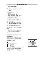
Page 6: ...ACK RIGHT BURNER CONTROL KNOB FRONT RIGHT BURNER CONTROL KNOB OVEN KNOB THERMOSTAT PILOTS IGNITION SWITCH ZANUSSI OVEN TOP GAS GAS MAIN 0 OVEN 0 HOT PLATE 2 3 4 5 1 6 0 2 3 4 5 1 6 HOT PLATE Hob 1 0kW 2 6kW 2 1 3 4 1 5kW 1 0kW 1 Front left Hot plate Ø145mm 2 Back left Rapid Hot plate Ø145mm 3 Back right burner auxiliary 4 Front right burner rapid ...

Page 7: ...g the oven the cover has to be opened to avoid over heating The electric oven is equipped with 3 heating elements 2 heating elements top and bottom for using the oven 1 heating grill element placed in the middle of top for grilling with door half opened Use The oven can be used in traditional cooking or for grilling but not simultaneously Control knob fig 1 It makes possible to choose the most app...

Page 8: ... the thermostat on position for about 10 min 2 Insert the meal Top heating element It is a radiant cooking The heat comes from the top of the oven only This position of the thermostat is recommended for warning up the cooked meals It is not necessary to preheat the oven fig 4 How to proceed 1 Insert the meal on the 3rd level fig 6 2 Turn the thermostat on position Electric grill When grilling the ...

Page 9: ...e guide 2 for thick pieces to be roasted beef bacon large fish poultry When the first side is brown turn the meat without pricking it in order that the juices are not lost Roast the second side Salt when ending the cooking Cooking time has to determined by the thickness of the piece to be roasted not by its weight Frying Put the grill deflector in place Fix the knob oven grill on position Place th...

Page 10: ...so that its end be in its place at the bottom of the oven and put it on the spit support Slide the dripping pan on an inferior support Pull out the handle Fix the oven grill control knob on position Check whether the spit turns For taking out the dish turn the knob to position off Fix the handle Remove slowly and simultaneously the dripping pan and the spit Pull out the spit using a thermal glove ...

Page 11: ... extinguish turn off the relevant control know leave for at least one minute and then re ignite If after a few attempts the burner does not ignite check that the burner ring and its cap are correctly positioned fig 12 Extinguishing of burners Turn the knob clockwise to mark The safety device is in place Do not put anything on the hob that is liable to melt Electric Hotplates To switch on a hotplat...

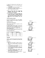
Page 12: ...fit to the diameter of the burner used fig 14 Chose thick flat bottom pots We recommend the flame is lowered as soon as the liquid starts boiling For a correct ignition always keep the burner ring and the spark plugs clean The following diameter pans can be used Good use Bad use Power waste fig 14 Diameter mm Burner Power kW min max Rapid 2 60 165 260 Auxiliary 1 00 120 160 Hot plate Always use po...

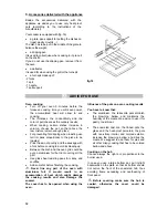
Page 13: ...y and the sausage with a fork before cooking to avoid its blowing up Between the dish and the oven grid could be put an aluminium foil but not covering all the grid Use glass heat resisting pans for crispy and soufflés Add some fat before finishing the cooking Never line any part of the oven with aluminium foil It would result in an accumulation of heat which might damage the cooking results and a...

Page 14: ... and leave it dissolving but do not scratch and avoid use of abrasive or caustic products that could damage the enamel Wipe immediately the stains of vinegar lemon generally the acid substances Hot plate Use a wet sponge and detergent rinse and dry If necessary heat beforehand the plate for burning the dirt The plates must be maintained dry From time to time you can wipe with an absorbant paper li...

Page 15: ... wet the burner cap and ring burner have been replaced correctly after cleaning the control knob has been pressed for 10 seconds upon ignition Check that the thermostat is placed correctly the cooking time is adapted the grill is placed correctly in the oven Check that the oven does not need cleaning the meal does not overflow there is no excessive fat juice projection on the oven sides Check that...

Page 16: ...r wrong installation non conforming to the rules imposed by the power water gas distributor if the user modified the material or took off the marking or the serial numbers if the person who made the repairing is not certified by the manufacturer or the dealer if the appliance was used for commercial or industrial purpose or other household purposes than what it was conceived for if the appliance w...

Page 17: ...opening between contacts of minimum3 mm Installation and maintenance have to be made by a qualified person in accordance with the regulations in force We deny any responsibility in cases of accidents or incidents caused lack of grounding or missgrounding INSTALLATION Placement Remove the plastic packaging and install the cooker in a dry ventilated room fig 20 not near curtains paper alcohol petrol...

Page 18: ...ed with its holder Make sure it is well inserted and fix it by means of a collar Flexible pipe fig 22 Flexible pipe mechanic connection max length 1 5 m We advice to use a flexible pipe according to the national rule in force not shorter than 1 m depending on the position of the tap Connect one end of the pipe to the blocking tap than before placing the appliance between the furniture connect the ...

Page 19: ...ED The manufacturer declines any liability should these safety measures not be observed Before switching on make sure the electricity supply voltage is the same as that indicated on the rating plate Note In case of a direct connection to the mains you have to interpose an omnipolar switch a minimum opening between contacts of 3 mm The switch should be sited within 2m of the hob and be easily acces...

Page 20: ... 230 V 400 V 230 V 400 V Voltage of heating elements 230 V 230 V 230 V 230 V Fusible capacity 20 A 16 A 10 A 16 A Cable section 3 x 2 5 mm 4 x 1 5 mm 5 x 1 mm 4 x 1 5 mm OVEN LAMP REPLACEMENT Before replacing the lamp take care that all control knobs be on off position 0 Disconnect the appliance watch that the oven be cool This lamp of 15 W convection E 14 230 240V is a special lamp for higher tem...

Page 21: ...es for every gas The whole of every nozzle is marked in microns on the nozzle For changing the nozzles 1 Remove the pan support 2 Remove the burners 3 Using a socket spanner 7 unscrew the nozzles fig 26 and replace them with those required for the type of gas in use see table no 2 4 Put in place the burners and the pan supports Adjustment of minimum level of plate burners When changing the gas typ...

Reviews: