background image

24

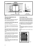
LEVELLING FEET

PENCIL LINE ON THE FLOOR

PLAN VIEW OF THE COOKER

580 mm.

100 mm.

300 mm.

295 mm.

WALL FACE

A

BACK OF COOKER

SIDE VIEW

OF THE COOKER

BASE OF COOKER

ENGAGEMENT EDGE FOR

STABILITY BRACKET

Fig. 3

Fitting the Stability Bracket
(Not supplied)

If the cooker has to be installed with a flexible supply

pipe, it is necessary that a stability device is fitted.

(See "Important Safety Requirements").

If a stability bracket should be fitted by the installer, these

instructions should be read in conjunction with the leaflet

packed with the stability bracket.

Place cooker in its intended position and level cooker.

Mark off 295mm (11 

1

/

2

") from the right hand side of the

cooker as shown, this is the centre line of the bracket

fixing.

Draw a line 100mm (4") from the front edge of the levelling

feet (see Fig. 17) and remove cooker from its position.

Mark off 580mm (23") back from this line on the centre

line of the bracket to locate the front edge of the lower

bracket.

Fix lower bracket (with two fixing holes) to the floor, then

measure height from floor level to engagement edge on

back of cooker, dimension 'A' of Fig. 2.

Assemble  upper  bracket  to  lower  bracket  so  that

underside of bracket is dimension 'A' +3mm (1/8") above

floor level. Re-position cooker and check that top bracket

engages into cooker back to a depth of 75mm (3"), as

shown in Fig. 2.

Should the stability bracket currently installed not allow

the cooker to stand correctly, ask the installer to replace

it with the correct type.

Fig. 2

Connecting to Gas

This cooker is designed to be installed with an appliance

flexible connection. Connection is made to the RC 1/2

(1/2" B.S.P.) threaded entry pipe located just below the

hotplate level on the rear right-hand side of the cooker.

Check for gas soundness after connecting the gas supply.

The gas bayonet connector must be fitted in the shaded

area indicated in Fig. 3. Take into account that it must

be possible to pull the cooker forward sufficiently. The

hose must not get caught on the stability bracket.

Note:

If using different types of gas bayonet connection, it may

not be possible for the appliance to be pushed fully back

to the wall stops.

Important:

Flexible  tubing  MUST  comply  with  BS.669  Current

Edition.

FO  0179

FO  0180

600

450

130

Summary of Contents for ZCM 600

Page 1: ...MIXED FUEL COOKER ZCM 600 ZCM 610 INSTRUCTION BOOKLET Please read this instruction booklet before using the appliance GB ...

Page 2: ... the cooker for a long period of time the ventilation should be improved by opening a window or increasing the extractor speed l Do not use this cooker if it is in contact with water Do not operate the cooker with wet hands l Ensure the control knobs are in the OFF position when not in use l When using other electrical appliances ensure the cable does not come into contact with the hot surfaces of...

Page 3: ...ed to the heat when the appliance is operated it is possible to fit a special protection device to the oven door This device can be purchased in our Service Force Centres specifying the relevant code 35791 and the Product No shown on the rating plate Important Safety Information 2 Guide to Use the instructions 3 Description of the Cooker 4 Control Panel 5 Before the First Use of the Cooker 6 Contr...

Page 4: ...is in the oven cavity 1 Unpack the splash back and dispose of the packaging with due regard to safety and the environment 2 Slide the two bayonets of the splash back into the relevant supports on the rear edge of the cooker s hob STOP SET TIME Description of the Cooker Splash back only in model ZCM 610 X Semi Rapid burner Rapid burner Control panel Shelf Ovendoor Semi rapid burner Auxiliary burner...

Page 5: ... Electric ignition push button 4 Back left burner control knob semi rapid 5 Front left burner control knob rapid 9 8 7 6 5 1 2 4 The Oven Cavity Grill element Oven Light Accessories Ovenfan 10 Grill trivet Grill roasting pan Removable handles 3 6 Front right burner control knob auxiliary 7 Back right burner control knob semi rapid 8 Oven function control knob 9 Oven thermostat control knob 10 24 h...

Page 6: ... should be heated without food During this time an unpleasant odour may be emitted This is quite normal 1 Set the electronic timer to manual function 2 Switch the oven function control knob to fan cooking 3 Set the thermostat control knob to MAX 4 Open a window for ventilation 5 Allow the oven to run empty for approximately 45 minutes This procedure should be repeated with the grill function for a...

Page 7: ...at comes only from the top element Electric Oven 0 1 0 0 1 5 0 2 0 0 5 0 Thermostat Control Knob Turn the thermostat control knob clockwise to select temperatures between 50 C and 250 C max To ensure maximum burner efficiency you should only use pots and pans with a flat bottom fitting the size of the burner used see table As soon as a liquid starts boiling turn down the flame so that it will bare...

Page 8: ...econds press button 2 12 00 will show in the display as Fig 4 Within 5 seconds press and hold either button 1 to decrease or button 2 to increase the time until the correct time of day on the 24 hour clock is reached e g 14 30 See Fig 5 NOTE The increase and decrease control buttons operate slowly at first and then more rapidly They should be pressed separately Fig 1 Fig 2 Fig 3 Fig 4 Fig 5 24 Hou...

Page 9: ...me on again once button 1 has been depressed When cooking is complete remove food and turn OFF oven temperature control 3 To cancel the timer Press and release button 1 Then press and hold button 1 and the display will count down in one minute intervals to 0 00 See Fig 10 Release button 1 After a few seconds the cookpot symbol will flash and the time of day will show in the display See Fig 11 If t...

Page 10: ...r than 30 cm x 35 cm 12 in x 14 in as they will restrict the circulation of heat and may affect performance The effects of dishes on cooking results Dishes and tins vary in their thickness conductivity colour etc which affects the way they transmit heat to the food inside them A Aluminium earthenware oven glassware and bright shiny utensils reduce cooking and base browning B Enamelled cast iron an...

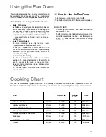
Page 11: ...e top shelf may brown slightly quicker than the lower one This is quite usual There is no mixing of flavours between dishes How to Use the Fan Oven 1 Turn the oven function control knob to 2 Turn the thermostat control to the required temperatu re THINGS TO NOTE l The oven light will come on when the oven function control knob is set l The thermostat control light will remain on until the correct ...

Page 12: ...ecommendations for oven temperatures given in the cooking charts but be prepared Hints and Tips Meat Thermostat Cooking Beef 170 180 C 20 30 min per 1 2 kg 1 lb and 20 30 min over Lamb 170 180 C 25 35 min per 1 2 kg 1 lb and 25 35 min over Pork 170 180 C 25 35 min per 1 2 kg 1 lb and 25 35 min over Chicken 170 180 C 15 20 min per 1 2 kg 1 lb and 20 min over Turkey and goose 170 180 C 15 20 min per...

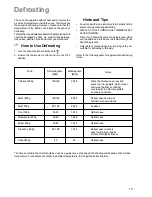
Page 13: ...at 500 g 90 120 20 30 As above Trout 150 g 23 35 10 15 Defrost open Strawberries 300 g 30 40 10 20 Defrost open Butter 250 g 30 40 10 15 Defrost open Cream 2 x 200 g 80 100 10 15 Defrost open cream is easy to whip even if parts of it are still slightly frozen Cake 1400 g 60 60 Defrost open Food Defrosting time Mins Standing time Mins Notes Hints and Tips Cover food with a lid aluminium foil or pla...

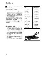
Page 14: ...irculation of air to lift the food out of the fats and juices Food such as fish liver and kidneys may be placed directly on the grill pan if preferred Food should be thoroughly dried before grilling to minimise splashing Brush lean meats and fish lightly with a little oil or melted butter to keep them moist during cooking Accompaniments such as tomatoes and mushrooms may be placed underneath the g...

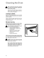
Page 15: ...upports are dishwasher proof If washing them by hand take care when drying them as the enamelling process occasionally leaves rough edges If necessay remove stubborn stains using a paste cleaner The pan support of this cooker is fitted with anti scratch rubber feet These feet are dishwasher proof and should not be removed when cleaning the pan support If the rubber feet become detached from the pa...

Page 16: ...shing up liquid has been added To prevent damaging or weakening the door glass panels avoid the use of the following Householddetergentandbleaches Impregnated pads unsuitable for non stick saucepans Brillo Ajax pads or steel wool pads Chemical oven pads or aerosols Rustremovers Bath Sink stain removers Clean the outer and inner door glass using warm soapy water Should the inner door glass become h...

Page 17: ...ob on fan oven and set the thermostat knob on 50 C 4 After 15 minutes turn off the thermostat and allow the fan oven to continue without heat for a further 5 minutes when the temperature of the water will have cooled down 5 Carefully remove the pan of water from the oven and use normal oven cleaners to clean away soil residues 6 Leave a little of the soapy water to soak into any burned on spillage...

Page 18: ...n is wired in properly and the socket switch or the switch from the mains supply to the oven are ON u Select a temperature with the thermostat control knob u Select a function with the oven function control knob u Check the light bulb and replace it if necessary see Replacing the Oven Light u The temperature may need adjusting u Refer to the contents of this booklet especially to the chapter Using...

Page 19: ...ironment plus those which are the subject to rental agreements Products of Zanussi manufacture which are not marketed by Zanussi European Guarantee If you should move to another country within Europe then your guarantee moves with you to your new home subject to the following qualifications The guarantee starts from the date you first purchased your product The guarantee is for the same period and...

Page 20: ...chty Fife KY14 7AJ BLANTYRE Unit 5 Block 2 Auchenraith Ind Estate Rosendale Way Blantyre G72 0NJ DUMFRIES 93 Irish Street Dumfries DG1 2 PQ DUNOON 7 Hill Street Dunoon Argyll PA23 7AL EDINBURGH Unit 12 Dumbryden Ind Estate 2 Dumbryden Road Edinburgh EH14 2AB GLASGOWUnit 4 Wellington Road Bishopriggs Glasgow G64 2SA INVERNESS Unit 3BI Smithton Ind Estate Smithton Inverness IV2 7WL ISLE OF ARRAN R H...

Page 21: ...d Enfield London EN3 7BB GRAVESEND Unit B4 Imperial Business Estate West Mill Gravesend Kent DA11 0DL IPSWICH Unit 6C Elton Park Business Centre Hadleigh Road Ipswich IP2 0DD LETCHWORTH 16 17 Woodside Ind Park Works Road Letchworth Herts SG6 1LA LONDON 2 4 Royal Lane Yiewsley West Drayton Middlesex UB7 8DL MAIDENHEAD Reform Road Maidenhead Berkshire SL6 8BY MOLESEY 10 Island Farm Avenue West Moles...

Page 22: ...ALFLOW RATE m3 h 0 286 0 057 0 190 0 038 0 095 0 028 NOZZLEREFERENCE 119 Adjust 96 Adjust 70 Adjust NOMINALTHERMAL POWERkW 2 8 0 65 2 0 0 45 1 0 0 33 NOMINALFLOW RATE g h 202 43 5 144 29 72 21 5 NOZZLEREFERENCE 86 40 71 32 50 28 NATURAL GAS 20 mbar TYPEOF GAS CHARACTERISTICS LPG GAS 28 30 37 mbar 1 100 mm 1 100 mm VALUE 49 92 MJ Kg VALUE 37 78MJ m3 Ws 50 7 MJ m3 Instructions for the Installer Hob ...

Page 23: ...fitted next to a side wall or cabinets above height of the hotplate trims then a gap of 115 mm is required Curtains must not be fitted immediately behind the cooker or within 115 mm of the sides of the cooker Note D Any wall cabinet or extractor must not be lower than 780mm above hotplate level Note E Wall cabinets may be fitted in line with the sides of the base units providing that the lower edg...

Page 24: ...en measure height from floor level to engagement edge on back of cooker dimension A of Fig 2 Assemble upper bracket to lower bracket so that underside of bracket is dimension A 3mm 1 8 above floor level Re position cooker and check that top bracket engages into cooker back to a depth of 75mm 3 as shown in Fig 2 Should the stability bracket currently installed not allow the cooker to stand correctl...

Page 25: ...n and yellow earth wire to the terminal in the plug which is marked with the letter E or the earth symbol or coloured green and yellow Connect the blue neutral wire to the terminal in the plug which is marked with the letter N or coloured black Connect the brown live wire to the terminal in the plug which is marked with the letter L or coloured red Upon completion there must be no cut or stray str...

Page 26: ...ntrol knob The adjustment screw is located down the centre of the gas tap control shaft To adjust use a thin bladed screwdriver and turn the adjustment screw until the flame is steady and does not extinguish when the knob is turned from MIN to MAX Repeat this procedure for all burners Pressure Testing Remove left hand pan support and front left burner cap and crown Fit manometer tube over the inje...

Page 27: ...ll pan supports burner caps rings crowns and control knobs With the aid of a 7mm box spanner the burner injectors can then be unscrewed and replaced by the appropriate LPG injectors see Technical Data To adjust the gas rate With the aid of a thin bladed screwdriver completely tighten down the by pass adjustment screw which is located down the centre of the gas tap control shaft Upon completion sti...

Page 28: ...lux Group The world s No 1 choice The Electrolux Group is the world s largest producer of powered appliances for kitchen cleaning and outdoor use More than 55 million Electrolux Group products such as refrigerators cookers washing machines vacuum cleaners chain saws and lawn mowers are sold each year to a value of approx USD 14 billion in more than 150 countries around the world ...

Reviews: