12
○
○
○
○
○
○
○
○
○
○
○
○
○
○
○
○
○
○
○
○
○
○
○
○
○
○
○
○
○
○
○
○
○
○
○
○
○
○
○
○
○
○
○
○
○
○
○
○
○
○
○
○
○
○
○
○
○
○
○
○
○
○
○
○
○
○
○
○
○
○
○
○
○
○
○
○
○
○
○
○
○
○
○
○
○
○
GB
Installation instructions
For easy installation, proceed as follows:
• Fix the wall brackets and Splashback
• Fix the canopy
• Connect the hood to the mains power supply and make sure that it works properly
• Set the hood for ducting or recirculation
• Fix the telescopic chimney
Fitting the wall brackets and Splashback
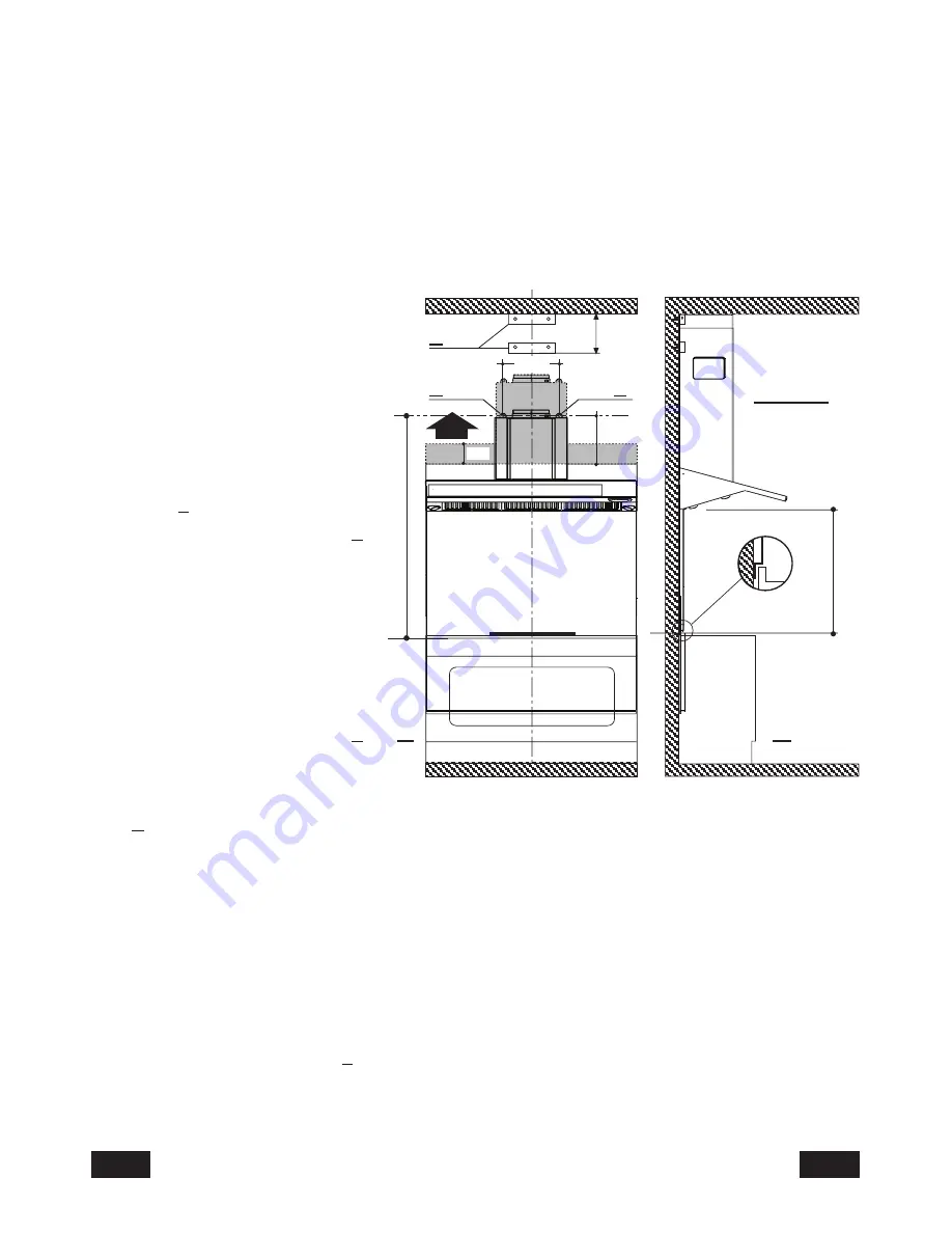
Please refer to (
fig.2a-b
):
•
Draw
a vertical line on the
wall, from the centre of the
cooking appliance up to the
ceiling, using a marking pen.
This is to ensure the correct
vertical alignment of the
various parts.
• Fixing the wall brackets
item 2:
a)
Place
one of the brackets
2
against
the
wall
approximately 1 or 2 mm
from the ceiling or from the
top limit, aligning its centre
(slot) with the vertical line.
b)
Mark
the centres of two
keyholes in the bracket on
the wall.
c)
Rest
the other bracket
2
against the wall, aligning it
with the vertical line, at a
distance
X
measured as shown in
fig. 2
equal to the height of the upper chimney element
S
supplied with the hood. The position
X
may vary, according to the various sizes of
upper chimney element available.
d)
Mark
the centres of the keyholes in the bracket on the wall.
• Drilling fixing holes item 1:
a)
Mark
a point on the vertical line at a distance from the cooking appliances of:
d
=1045 min (distance without splashback).
d
=height of splashback + 395 mm (distance with splashback).The distance
H
is the
minimum height in mm from the cooking appliances to the bottom edge of the front panel
of the hood.
b) At the point marked, draw a horizontal line parallel to the cooking appliances.
c)
Drill
two holes in the wall
1
using an 8 mm drill bit (fig.2a ), and insert the rawl plugs and
screws into the holes 1 (4.2 x 44.4 screws). Fix the screws, leaving a space of 5-6 mm
required to hook up the canopy. Small adjustments can be made using the hood adjustment
screws (see Fitting the canopy). The hood should have a maximum excursion of 20 mm.
232
195
1
1
2
20
X
H min 650
d = 1045 min
Fig. 2
a
b


