background image

15

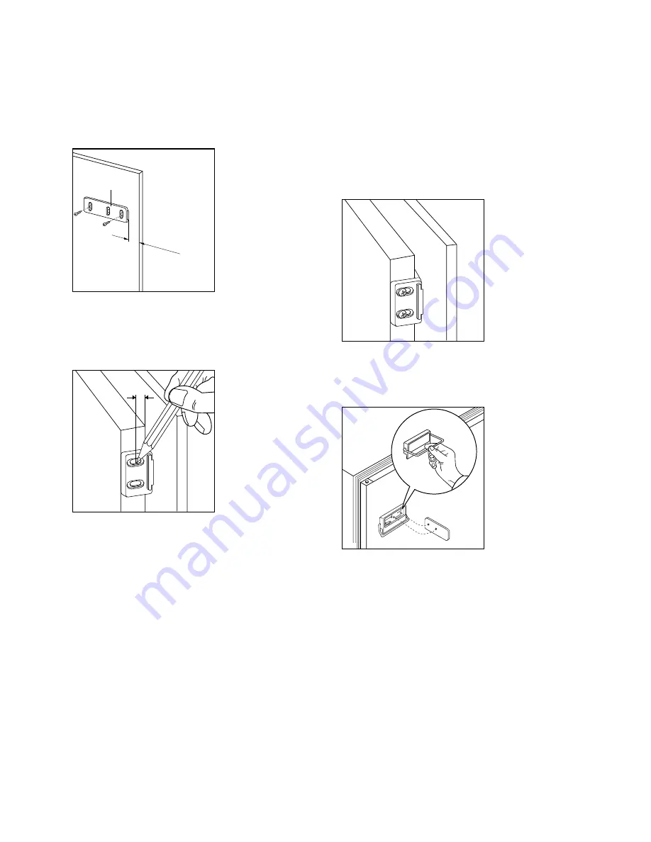
Position the runners (H) at the top and bottom of 
the inside of the kitchen unit as shown in Fig. 8 and 
mark the position of the external holes.
After preparing the holes, screw the runners to the 
kitchen unit door using 3.5x16 mm screws.

Fig. 8

Open both the appliance door and that of the 
kitchen unit to approx. 90

°

.

Place the little plates over the runners. Hold  the 
doors of the appliance and the unit together and 
mark the holes.

Fig. 9

D094

20mm

H

8mm

PR34

Remove the little plates and make the holes with a 
diam. of 2 mm. Replace the little plates over the 
runners and screw in the screws provided 
(3.5x16 mm).
For the alignment of the kitchen unit door, if 
necessary, use the clearance size of the slotted 
holes.
At the end of the procedure, check that the doors of 
the appliance and the kitchen unit open properly.

Fig. 10

The upper compartment can be opened by means of 
the sliding system illustrated in the previous point, 
or else by attaching on the door the handle which is 
supplied as an accessory (see figure).

Fig. 10a

PR35

D029

Summary of Contents for ZI 5280 D

Page 1: ...REFRIGERADOR CONGELADOR FRIDGE FREEZER FRIGOR FICO CONGELADOR ZI 5280 D LIBRO DE INSTRUCCIONES INSTRUCTIONBOOKLET MANUAL DE INSTRU ES 2222 014 82...

Page 2: ...conditions Please fill in the necessary details on the Card Certificate and send it to the Zanussi Centre covering the area in which the appliance is to be installed See list of Zanussi network centre...

Page 3: ...n instructions Parts which heat up should not be exposed Wherever possible the back of the product should be against a wall Before any cleaning or maintenance work is carried out be sure to switch off...

Page 4: ...arth or ground tap The supply lead plug in fact incorporates a special earth or ground contact for this purpose If by any chance the socketsofyourdomesticwiringsystemarenotearthed the appliance must b...

Page 5: ...together with the appliance on the stop strip A Fig 4 D033 50 min cm 200 2 min cm 200 2 A D015 D265 A Open the door and push the appliance against the side of kitchen furniture opposite to that of app...

Page 6: ...d mark the holes Fig 9 D094 20mm H 8mm PR34 Remove the little plates and make the holes with a diam of 2 mm Replace the little plates over the runners and screw in the screws provided 3 5x16 mm For th...

Page 7: ...ly and completely frozen and to make it possible subsequently to thaw only the quantity required at the time Wrap up the food in aluminium foil or polythene and make sure that the packages are airtigh...

Page 8: ...are equipped with a series of runners so that the shelves can be positioned as desired Positioning the door shelves To permit storage of food packages of various sizes the door shelves can be adjusted...

Page 9: ...iner complete defrosting should be carried out as follows pull out the plug from the wall socket or turn the thermostat knob to the O setting remove any stored food wrap it in several layers of newspa...

Page 10: ...oor is open and the light does not come on check that the bulb is properly screwed in if it still does not work replace the bulb with one of the same power The maximum rating is shown on the light cov...

Reviews: