background image

16

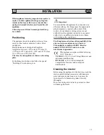
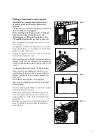
 Location

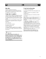
This appliance is designed to be built-in to a space 
having the dimensions given in Fig. 1.

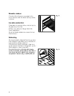
The height of the appliance can be altered if required 
by means of adjustable feet situated at its base 
(Fig. 2).

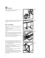
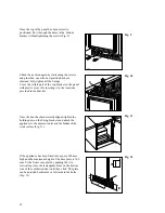
Door reversibility

Remove the two screws which fix the upper hinge to 
the door.
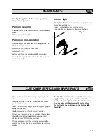
Carefully lean the appliance on its back and remove 
the plastic insert (Fig. 3).

Remove the two screws which fix the lower hinge to 
the door.

Remove the four screws which fix the lower hinge to 
the base of the appliance and remove the hinge itself; 
be very careful to recover all the screws.

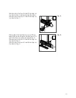
Remove the four screws that fix the upper hinge to the 
appliance and remove the hinge itself.

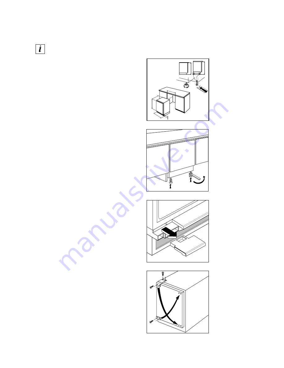
Take the hinge removed from the upper part of the 
appliance on the opposite side (see Fig. 4), and, using 
the screws removed from the lower part, fix it to the 
base of the appliance itself.

Remove and refit the other hinge on the upper part of 
the appliance on the opposite side.
Fix the two front screws into the upper and lower 
hinges (Fig. 4).

Finally, check the alignment of the door and make 
sure it closes properly.
After having reversed the opening direction of the 
door, discard the original plastic insert removed and 
fit the insert supplied with the appliance on the 
opposite side.

Fig. 1

Fig. 2

Fig. 3

Fig. 4

100-170

596

820-870

547 

550 

600

820

870

D506

D507

D447

D510

Summary of Contents for ZR 170 UN

Page 1: ...FRIGORIFERO REFRIGERATOR KÜHLSCHRANK REFRIGERATEUR ZR 170 UN LIBRETTO ISTRUZIONI INSTRUCTION BOOKLET GEBRAUCHSANWEISUNG MODE D EMPLOI 2222 260 07 ...

Page 2: ...rcumstances should solid ice be forced off the liner Solid ice should be allowed to thaw when defrosting the appliance See defrost instructions ª Do not place carbonated or fizzy drinks in the freezer as it creates pressure on the container which may cause it to explode resulting in damage to the appliance Installation ª There are working parts in this product which heat up Always ensure that ther...

Page 3: ...oor panel 17 Technical specification 20 ª Electrical connection 20 Use 21 ª Operation 21 ª Temperature regulation 21 ª Fresh food refrigeration 21 ª Movable shelves 22 ª Ice cube production 22 ª Defrosting 22 Maintenance 23 ª Periodic cleaning 23 ª Periods of non operation 23 ª Interior light 23 Customer service and spare parts 23 GB ...

Page 4: ...urpose the supply cable plug incorporates a special earth contact If the sockets of your domestic wiring system are not earthed have the appliance connected to a separate earth wire by a qualified electrician in accordance with existing safety regulations The Manufacturer declines all responsibility if the above safety precautions are not observed This appliance complies with EEC directive number ...

Page 5: ...l the screws Remove the four screws that fix the upper hinge to the appliance and remove the hinge itself Take the hinge removed from the upper part of the appliance on the opposite side see Fig 4 and using the screws removed from the lower part fix it to the base of the appliance itself Remove and refit the other hinge on the upper part of the appliance on the opposite side Fix the two front scre...

Page 6: ...With a tape measure or similar instrument measure distance A between the top edge of the door and the top edge of the decorative panel placing it next to the recess Lay the panel face down Fig 6 Position the top bracket on the panel making sure that there is an equal distance between it and the sides and that its distance from the top edge is equal to distance A less 1 cm Secure the bracket with t...

Page 7: ... in the bracket Once the door has been correctly aligned tighten the holding nuts on the fixing brackets and attach the appliance to the adjacent units and the bottom of the work surface Fig 11 If the appliance has been fitted into a space 820 mm high and the maximum height of the base plate is 100 mm fit the front cover plate by pushing the two vertical lugs into the rectangular holes on the bott...

Page 8: ...12 If the appliance has been fitted into a space 870 mm high and the maximum height of the base plate is 150 mm fit the front cover plate as described in Fig 13 If the base plate is between 150 and 185 mm high cut it as shown in Fig 14 If the base plate is between 185 and 220 mm high cut it as shown in Fig 12 Fig 13 Fig 14 100 150 820 870 20 80 D519 100 135 150 185 820 870 D520 ...

Page 9: ...ide the appliance Electrical connection Before plugging in ensure that the voltage and frequency shown on the serial number plate correspond to your domestic power supply Voltage can vary by 6 of the rated voltage For operation with different voltages a suitably sized auto transformer must be used GB ...

Page 10: ...y causing frost to form on the rear wall In this case the dial must be set to a higher temperature to allow automatic defrosting and therefore reduced energy consumption Fresh food refrigeration To obtain the best performance do not store warm food or evaporating liquids in the refrigerator do cover or wrap the food particularly if it has a strong flavour Position food so that air can circulate fr...

Page 11: ...move the trays from the freezer Defrosting Frost is automatically eliminated from the evaporator of the refrigerator compartment every time the motor compressor stops during normal use The defrost water drains out through a trough into a special container at the back of the appliance over the motor compressor where it evaporates To prevent the water overflowing and dripping onto the food inside pe...

Page 12: ...s shown in the figure Fig 17 D731 CUSTOMER SERVICE AND SPARE PARTS If the appliance is not functioning properly check that the plug is firmly in the wall socket and the mains power switch is on there is an electricity supply find out by plugging in another appliance the thermostat knob is in the correct position If there are water drops on the bottom of the cabinet check that the defrost water dra...

Reviews: