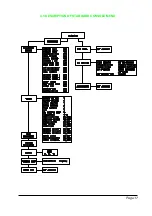
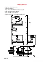
background image

Page 28

9

VFIELD NOT OK
This test is made at standby with the Main Contactor open.  In this condition the
voltage on both the connections of field must be to around 1/ 2 VBatt. This alarm is
generated if the field voltage is different from this value. Possible causes:

a) Frame fault on the motor to chassis.

b) Incorrect connection of the field winding to the chopper.

c) Failure of the chopper in the section  relative to the field.

10 VACC NOT OK

This Alarm is generated if the accelerator output voltage  differs more than 2V from
the acquired minimum during the PROGRAM VACC.  Possible causes:

a) The track of the potentiometer has become open.

b) The potentiometer  is not wired correctly.

c) The potentiometer itself is defective.

d) The values set in PROGRAM VACC routine have not remained or made cor-

rectly.

11 PEDAL WIRE KO

This Alarm is generated if potentiometer or wiring fault is detected. (NPOT or
PPOT are open circuit).

12 STBY  I  HIGH

This test is made during the initial diagnosis and at standby.  The test verifies that
the current is zero. This Alarm disables the machine.  Possible causes:

a) Defective current sensor.

b) Logic failure. First replace the logic. If fault remains replace the power unit.

13 I = 0 EVER

This check is made during travel. If the current is not higher than a preset minimum
value, this Alarm is generated and the machine disabled. Possible causes:
see STBY I HIGH.  Check the motor armature (brush connections).

14 HIGH FIELD CURR, NO FIELD CUR

Problem detected with the field winding current.  Possible causes:

a) Tailure of the field current sensor.

b) Field cables not connected or incorrectly connected.

c) Open circuit Field Winding.

d) Failure of the Field Power Unit.

e) The Alarm No FIELD CURR could also be generated if the safety microprocessor

detects a problem.

15 CONTACTOR DRIVER, COIL SHORTED, DRIVER SHORTED

These Alarms are generated if there is a problem with the Main Contactor. Possible
causes:

a) the coil of the contactor is either short-circuit, open circuit, or not connected

b) The Contactor Coil Driver is  short-circuit.

c) defect in the wiring to the contactor, or logic failure.

Summary of Contents for SEM2

Page 1: ...ns 14 3 6 Mechanical Drawing Dimensions 15 4 Programming Adjustments using Digital Console 16 4 1 Adjustments via Console 16 4 2 Description of Console Connection 16 4 3 Description of Standard Consol...

Page 2: ...d at times indicated 37 The information contained in the paragraphs marked with this symbol is essential for the purpose of safety SIGNED IN APPROVAL COMPANY DEPT SERVICES MANAGEMENT EXECUTIVE ENGINEE...

Page 3: ...meter Negative supply PAUX Positive supply for auxiliary load PB Brake pedal switch PPOT Potentiometer Positive supply REV Reverse switch input SR1 Speed Reduction 1 Microswitch SR2 Speed Reduction 2...

Page 4: ...r Various chopper configurations can be selected by the user without the need for hardware modifications Future technological updates are made easy for the user The communication protocol will continu...

Page 5: ...ON MAXIMUM CURRENT BOOSTER CURRENT VOLTAGE DROP AT TOTAL CONDUCTION 24V 500A 500A 580A 0 25V at 200A 25 C 36V 500A 500A 580A 0 25V at 200A 25 C 48V 350A 350A 400A 0 25V at 100A 25 C 2 2 CONTROL UNITS...

Page 6: ...associated with the potentiometer especially relating to the minimum level The two graphs show the output voltage from a non calibrated potentiometer with respect to the mechanical zero of the control...

Page 7: ...erations are not carried out correctly Requests for drive must be made after closing the key Switch Protection against uncontrolled movements The Main Contactor will not close if The Power Unit is not...

Page 8: ...losed if the motor is rotat ing the chopper controls the speed and automatically brakes and keeps the motor at a very low speed during descent on a gradient This is a very useful safety feature and is...

Page 9: ...Led connected to Connector A will flash a certain number of times for a given Alarm See Listings or the Digital Console may be used A permanent Alarm will be displayed on the Console immediately and...

Page 10: ...traction battery Do not use the outputs of convertors or power supplies For special applications please contact the nearest Zapi service centre Start the machine the first time with the drive wheel s...

Page 11: ...and battery use cable of 25 to 35mm section For the Field connections use cable of 4mm section For the optimum chopper performance the cables to the battery should be run side by side and be as short...

Page 12: ...roswitches B3 PTG Positive Supply to Main Contactor B4 BRUSH SR2 Input from motor brush switch normally open or Input from second speed reduction switch normally closed B5 HB Input from Hand Brake Swi...

Page 13: ...ve Serial Reception G3 PCLTXD Positive Serial Transmission G4 NCLTXD Negative Serial Transmission G5 Batt Negative supply to Digital Console G6 VL Positive supply to Digital Console G7 Free G8 Free L1...

Page 14: ...s case the Nor mally Closed microswitches need to be Normally Open and the Normally Open Microswitches need to be normally Closed 3 The MOTOR THERM BACK FW BACK REV ENABLE SR3 FREE inputs could be con...

Page 15: ...Page 15 3 6 MECHANICAL DRAWING DIMENSIONS...

Page 16: ...ade using the Digital Console The Console is connected to the G connector of the SEM 2 Chopper Pay attention to the polarity of the Console Connector when connecting to the chopper The bevel on the co...

Page 17: ...Page 17 4 3 DESCRIPTION OF STANDARD CONSOLE MENU...

Page 18: ...2 TRACTION Input for 3 Wire Potentiometer 3 Speed Reductions Input for Tiller Switch or Seat Switch delayed Input for Brake Pedal Microswitch Input for Motor Thermal Switch Management of Backing Speed...

Page 19: ...vides an input signal from the motor brushes OPTION 2 The Brush Switch Input may be used as a Second Speed Reduction 3 ENABLE SWITCH PRESENT The Enable Switch provides an input from the pedal accelera...

Page 20: ...ring up the next the Option 9 A new Option appears on the Display 10 When the desired Option is displayed press PARAM Top Right or SET Bottom Right button to change the configuration 11 The new Config...

Page 21: ...current above which the Field Current is at least the Nominal Value FIELD NOM CURR regardless of accelerator position 8 FIELD NOM CURR Nominal Field Current This parameter fixes the minimum Field Curr...

Page 22: ...DELAY 0 1 2 3 4 5 6 7 8 9 RELEASE BRAKING 0 1 2 3 4 5 6 7 8 9 PEDAL BRAKNG 0 1 2 3 4 5 6 7 8 9 INVERS BRAKING 0 1 2 3 4 5 6 7 8 9 TRACTION I MAX IMax 82 84 85 87 89 91 93 95 97 100 ARMA CUR NOM ACN IM...

Page 23: ...The names of the Parameters appear on the Display 8 When the desired Parameter appears the Display will show a Level Number that will be between 0 and 9 press either PARAM Top Right or SET Bottom Rig...

Page 24: ...Page 24 5 4 SEM 2 TRACTION STANDARD WIRING DIAGRAMS...

Page 25: ...adjustments to CUTBACK SP 1 2 3 Check the performance with the accelerator pedal totally depressed If the machine is a forklift check the performance with and without load 9 RELEASE BRAKING Operate th...

Page 26: ...AL WIRE KO Problem in the wiring of Foot Pedal 5 NO FIELD CUR Open Circuit Field Winding or failure of the Field Current Sensor 5 HIGH FIELD CUR Incorrect connection of Field Winding or fail ure of th...

Page 27: ...ers 4 INCORRECT START Alarm generated by an incorrect Starting Sequence Possible causes a The ENABLE microswitch has welded or failed b Error in the starting sequence from the operator c Error in the...

Page 28: ...e during the initial diagnosis and at standby The test verifies that the current is zero This Alarm disables the machine Possible causes a Defective current sensor b Logic failure First replace the lo...

Page 29: ...appears with a cold motor a Check the connection to the temperature sensor b Check that there is no problem with the temperature sensor c Check there is no problem with the motor temperature 18 TH PRO...

Page 30: ...n on the Left Hand Side of the Console Display and the value in percentage is shown on the Right Hand Side 9 FORWARD SWITCH the level of the Forward direction digital entry MA pin E3 ON VB active entr...

Page 31: ...ure of the motor within the limits Sensor is not operating Flow Chart showing how to use the TESTER function of the Digital Console 1 Opening Zapi Display 2 Press ENTER to go into the General menu 3 T...

Page 32: ...ing how to use the SAVE function of the Digital Console 1 Opening Zapi Display 2 Press ENTER to go into the General menu 3 The Display will show 4 Press ROLL UP or ROLL DOWN button until SAVE PARAM ap...

Page 33: ...how tto use the RESTORE function of the Digital Console 1 Opening Zapi Display 2 Press ENTER to go into the General menu 3 The Display will show 4 Press ROLL UP or ROLL DOWN button until RESTORE PARAM...

Page 34: ...ening Zapi Display 2 Press ENTER to go into the General menu 3 The Display will show 4 Press ROLL UP or ROLL DOWN button until PARAMETER CHANGE appears on the display 5 The Display will show 6 Press E...

Page 35: ...on until PROGRAM VACC appears on the display 5 Tthe Display will show 6 Press ENTER to go into the PROGRAM VACC routine 7 The Display will show the minimum and maximum values of potentiometer wiper ou...

Page 36: ...ected 200A Air Fuse C16520 6 3A 20mm Control Circuit Fuse P99060 Red LED C12373 9 Way Molex Connector C12372 8 Way Molex Connector C12371 3 Way Molex Connector C12370 2 Way Molex Connector C12769 Inse...

Page 37: ...level Check every 3 months Check the mechanical operation of the Contactor s Moving contacts should be free to move without restriction Check every 3 months Checks should be carried out by qualified p...

Page 38: ...INSTALLATION AND USER MANUAL CHOPPER SEM2...

Reviews: