Page 31
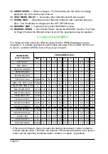
16) CUTBACK SWITCH 3: the level of the Speed Reduction 3 Microswitch (Pin L4).
ON/ +12 = active entry of speed reduction microswitch.
OFF / GND = non active entry of microswitch.
17) BRAKE SWITCH: the level of the Pedal Brake Microswitch (pin E5).
ON/+ VB = active entry of Brake pedal microswitch.
OFF / GND = non active entry of microswitch.
18) BACKING FUNCTION: the level of the Backing Microswitch inputs (pins L2 or L3).
ON/+ VB = active switch entry.
OFF / GND = non active switch entry.
19) MOTOR TEMPERAT.: the level of the Motor Temperature Sensor (pin E7).
ON / +VB = temperature of the motor is too high.
OFF/ GND = temperature of the motor within the limits. Sensor is not operating.
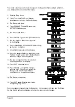
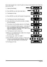
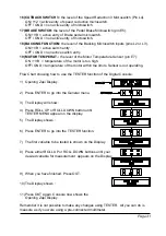
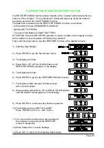
Flow Chart showing how to use the TESTER function of the Digital Console.
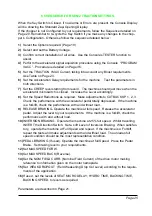
1) Opening Zapi Display.
2) Press ENTER to go into the General menu.
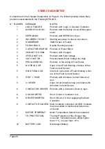
3) The Display will show :
4) Press ROLL UP or ROLL DOWN button until
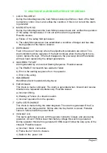
TESTER MENU appear on the display.
5) The Display shows :
6) Press ENTER to go into the TESTER function.
7) The first variable to be tested is shown on the Display.
8) Press either ROLL UP or ROLL DOWN buttons until your
desired variable for measurement appears on the Display.
9) When you have finished, Press OUT.
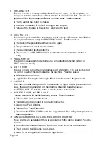
10) The Display shows :
11) Press OUT again. Console now shows the
Opening Zapi Display.
Remember it is not possible to make any changes using TESTER. All you can do is
measure as if you were using a pre-connected multimeter.

