AUTOMATIC GATE OPENER
• Installation Manual
16
Secure the Gate Bracket and the Post
Mount Bracket Assembly to the Gate and
the Gate Post
Step 5
Mark the bolt-hole locations on the gate and the gate
post. Do this by placing a punch or a mark in the mid-
dle of each bolt slot on the gate bracket and the post
mount bracket assemblies. (Marking the bolt-hole loca-
tions in the middle of each bolt slot permits slight
adjustments to the mounting brackets.)
Once you have marked the bolt-hole locations on the
gate and the gate post, remove the gate bracket and
the post mount bracket assembly by taking off the C-
clamps.
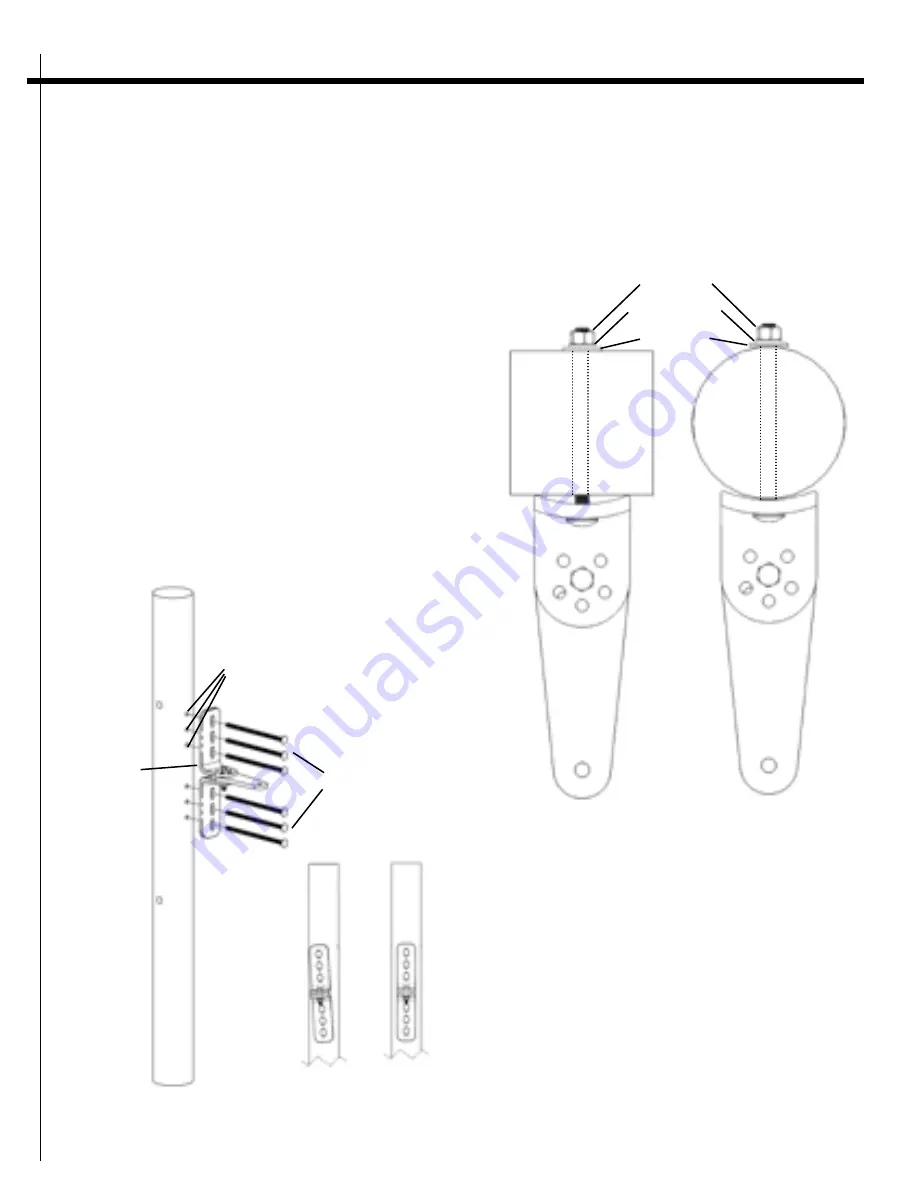
Step 6
(fig. 16)
Using a drill and a 3/8” bit, drill holes through the gate
post and the gate at the marked bolt-hole locations.
NOTE:
When drilling holes into the gate post and the
gate, keep the drill level and ensure the holes come out
at 180° on the other side.
Step 7
(fig. 17)
Attach the post mount bracket assemblies to the gate
posts by inserting six 3/8” x 8” carriage bolts though
each post mount bracket assembly and the drilled holes
in the gate post. Fasten each carriage bolt with one
3/8” washer, one 3/8” lock washer, and one 3/8” hex
nut.
Post bracket
assembly
Mark fence post and
drill 3/8” holes
3/8” x 8”
bolts
Figure 16
3/8” washer
3/8” x 8”
carriage bolts
Figure 17
3/8” lock washer
3/8” hex nut
INCORRECT!
Post bracket
NOT straight
CORRECT!
Post bracket
is straight


