Entrapment Alarm
(UL 325; 30.1)
In compliance with UL 325 the Zareba Automatic Gate
Opener is designed to stop and reverse direction within
two seconds of sensing an obstruction. In addition, the
Zareba opener activates an audible alarm if the unit
incurs an obstruction twice while opening or closing.
This alarm sounds for five minutes, or until the opener
receives a renewed, intended input from a hardwired
control such as the Push Button Control. At that point
the gate returns to a fully open or fully closed position.
Turning the power switch on the control box OFF and
back ON also deactivates the alarm.
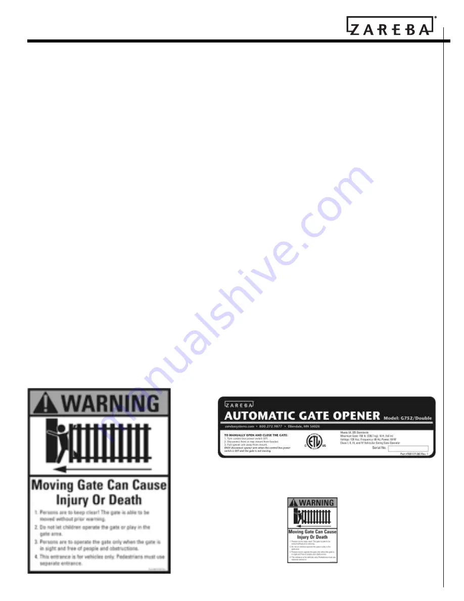
Warning Signs and Labels
Required Safety Precautions for Gates
WARNING SIGNS
alert people of automatic gate opera-
tion. They are
required
when installing the Zareba
Automatic Gate Opener. If pedestrians will be in the
area, install a walk-through gate for their use.
Warning Signs
The warning signs (
fig. 3
) must be installed on both
sides of the gate.
These warning signs and labels (
fig. 4-5
) must appear
at the locations specified below. If any were missing
when the gate opener was purchased, immediately
contact Zareba Systems for replacements.
7
Protection Against Entrapment
The Zareba Automatic Gate Opener is designed to com-
ply with UL 325, the safety standard covering automatic
gate opening systems. UL 325 requires that gate open-
ing systems have provisions for, or be supplied with, at
least one independent primary and one independent
secondary means of protection against entrapment. The
primary means of entrapment protection in the Zareba
Automatic Gate Opener is Type A, an inherent means of
entrapment protection. The secondary means of entrap-
ment protection in the Zareba Automatic Gate Opener
is Type B2, the provision for the connection of a contact
sensor (edge sensor).
The gate opener’s built-in means of entrapment protec-
tion (Type A) may not be sensitive enough to prevent
bodily injury in some circumstances. Secondary means
of entrapment protection (Type B2), such as contact
(safety edge) sensors are suggested for enhanced safety.
See
page 10
for important information on additional
safety devices.
Figure 3
Warning signs (two enclosed) to be
installed on each side of the gate (three to
five feet above the bottom of the gate)
Figure 4
Product identification and manual operation instruction label
installed on control box cover
Figure 5
Warning labels,
one on each side of
gate opener arm


