background image

1: Install the Loftmaster

Installation
Marking Out

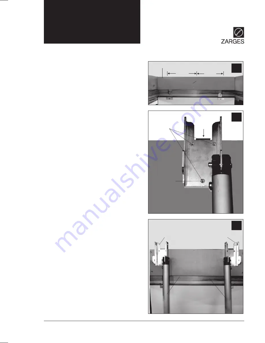
1.1   Measure and draw the ‘centre line’
on the ceiling joist midway across the
width of the loft opening where the
mounting brackets will be fitted, Fig 1.1.

Measure 188 mm either side of this line
and draw a vertical line at these points
greater than 90 mm long to mark the
mounting bracket centre lines.

1.2   Refer to Fig 1.2 and Fig 1.3. The
brackets are supplied with their ladder
sub-frame carrier tubes fitted. Note that
these brackets are ‘handed’, left bracket
and right bracket.

Take the first bracket and place it on the
mounting board so that it is placed over
the bracket centre line and slide it until
the lower screw hole is centred on this
line. Mark the centre point of this hole.

Fixing the Brackets

1.3   Remove the bracket and drill a 4mm
diameter hole at the position just
marked.

Fix the bracket using one of the fixing
screws supplied. Similarly drill the other
three holes (one on top) and screw in
the other screws. Repeat for the other
bracket, see Fig 1.3.

For more information visit: zarges.com/uk

7

1.1

1.3

Ceiling Joist

Left Mounting
Bracket 

Left Mounting

Bracket 

Ceiling Joist

Sub-Frame

Carrier Tubes

188mm

Centre Line

............

............

............

188mm

1.2

Mounting Bracket
Fixing Positions 

Ceiling Joist 

Left Mounting
Bracket 

Summary of Contents for 101482

Page 1: ...lescopic Loftmaster Safety Please ensure you read the Safety section in this manual before installing or using the equipment Your safety and that of others is paramount to ZARGES 101483 2 9m e Safety...

Page 2: ...se Spare parts are readily available You may already be familiar with using similar equipment but the Telescopic Loftmaster is unique and we recommend you take time and read these instructions They co...

Page 3: ...rations General Do not install or use the ZARGES Telescopic Loftmaster if damaged in any way Never exceed the maximum load of 150 kg Never operate any of the red buttons while on the ladder or allow a...

Page 4: ...so that the door opens downwards Permanently fitted in the loft Allows loft hatch to close when stowed a way Very easy to operate and use For more information visit zarges com uk 4 Loft door Floor to...

Page 5: ...3 Swivel arms x2 4 Hinge swivel pins x2 5 Ladder sub frame carrier bar x1 6 Ladder sub frame carrier tubes x2 7 Springs x2 8 Telescopic pole with hook x1 9 Bracket fixing screws x8 10 Instructions Fo...

Page 6: ...wo fixing brackets supplied must be attached to a secure part of the loft structure such as a ceiling joist or sound timber bridging and securely fastened to the joists Footprint When the ladder is op...

Page 7: ...ke the first bracket and place it on the mounting board so that it is placed over the bracket centre line and slide it until the lower screw hole is centred on this line Mark the centre point of this...

Page 8: ...lation will now be at the stage shown in Fig 1 6 Attaching the Springs 1 7 Slide the Ladder sub frame carrier bar into the hole in one of the sub frame carrier tubes see Fig 1 7 Now slide the two spri...

Page 9: ...ame carrier tube above the horizontal and pull the string to extend the spring so that it reaches and clips on to the hinged swivel pin see Fig 1 9 and inset for close up of spring on the pin Remove t...

Page 10: ...sioned springs will hold it in this position see Fig 1 13 Adjusting the Ladder Length 1 14 The ladder length can be extended by 15cm or 30cm from its minimum length to best suit your floor to floor he...

Page 11: ...ws no extension 1 18a Shows the end cap rotated 90 clockwise to the 15 cm extension position 1 18b Shows the end cap rotated 180 clockwise to the 30 cm extension position 1 18c and d Now carefully pul...

Page 12: ...with the top of the ladder close to the swivel arms Climb the ladder and enter the loft to gain access the top of the ladder Screw to the Swivel Arms 1 21a Align the holes in the swivel arm with the t...

Page 13: ...you can now place the stowage bracket see Fig 2 4 onto the sub frame carrier bar then do so and ignore paragraph 2 3 2 3 Insert the plain end of pole into the holes in rung 1 and rung 2 and lift up th...

Page 14: ...1 and rung 2 Push the pole up to un hook the ladder stowage bracket on the rear of rung 1 from the sub frame carrier bar and carefully lower the ladder Remove the Pole 3 3 Grip the lower stiles of th...

Page 15: ...opic Loftmaster is covered by a 12 month warranty The Company undertakes to replace or repair free of charge any defect which the Company considers to be due to faulty workmanship or material within 1...

Page 16: ...it 8 Holdom Avenue Saxon Park Industrial Estate Bletchley Milton Keynes MK1 1QU Tel 01908 641118 Email sales zarges co uk Web zarges com uk 8 Holdom Avenue Saxon Park Industrial Estate Bletchley Milto...

Reviews: