zBOOST® YX645 USER GUIDE
12
zBOOST® YX645 USER GUIDE
13
Solid GREEN
Normal condition at power up
.
Slowly Alternating RED and GREEN
zBoost® is working, but at reduced
performance and coverage due to “non-
ideal” setup.
Solution:
Increase the distance
betweenSignal Antenna and Base Unit
to achieve maximum performance and
coverage.
Fast Flashing RED
Indicates insuffi
cient distance between
the antenna and the amplifi er. Th
e
amplifi er is operating at signifi cantly
reduced coverage.
Solution:
Increase space between base
unit and antenna.
Solid RED
System is receiving signals from either
the mobile device or the base station
transceiver which are too strong for
proper operation.
Solutions:
Move away from
receiving antenna with your cell phone.
Move antenna away from other
devices..
Fast Alternating RED and GREEN
followed by no light
Th
e amplifi er is disabled.
Solution:
Unplug and start over.
zBoost® Base Unit Light Indicators
At Initial Power Up Only
Solid GREEN
Normal condition.
Solid RED
System is receiving signals from either
the mobile device or the base station
transceiver which are too strong for
proper operation.
Solution:
Please unplug your system.
Re-orient your Signal Antenna and/or
Base Unit to reduce the excessive signal
source. Plug your system back in. If
still solid red, call customer support
1-800-871-1612.
After Initial Power Up
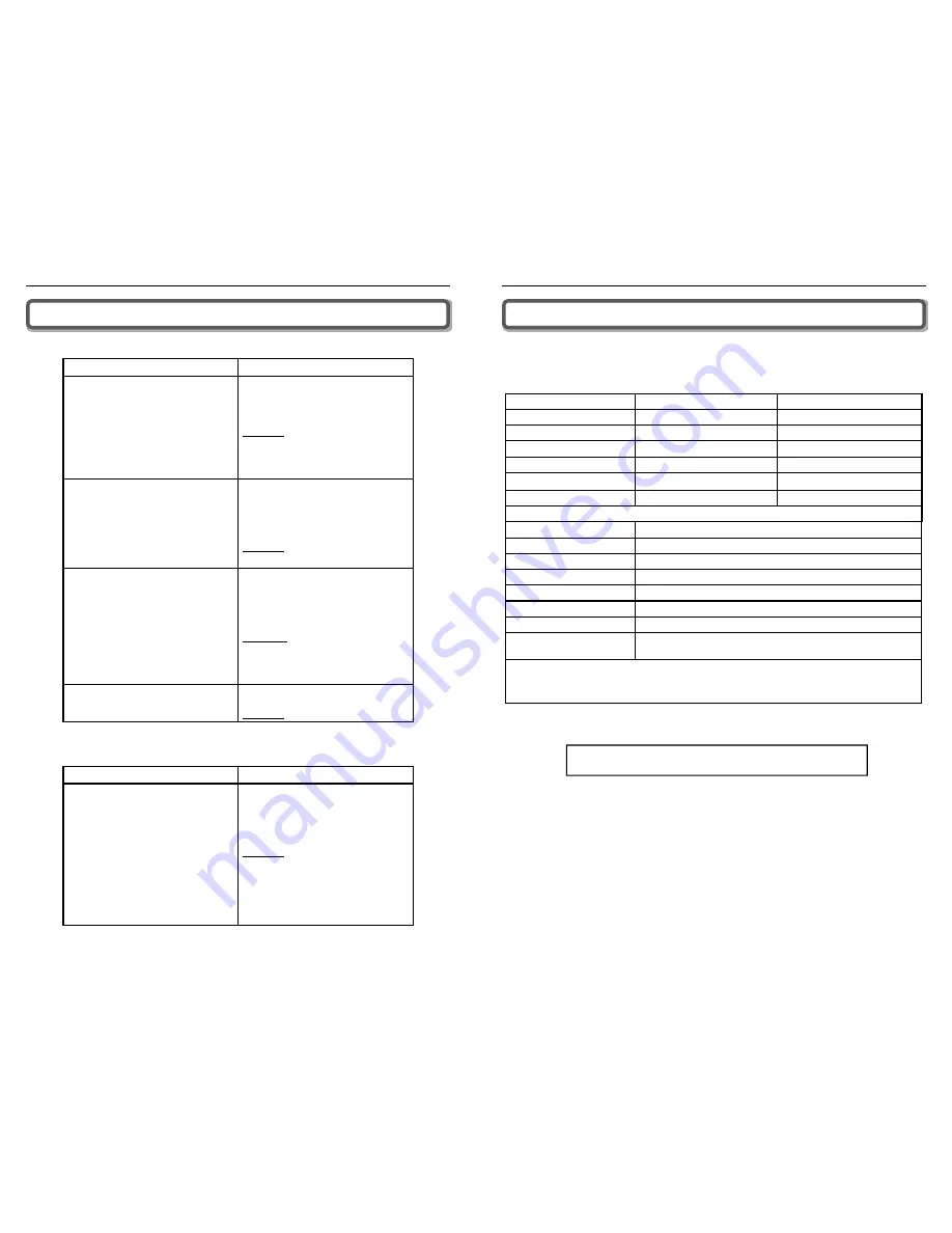
Technical Specifi cations
Th
is product is covered by patent US 7,706,744. Other U.S.
and foreign patents pending.
YX645 PCS-CEL Technical Specifi cations
PCS Frequency
CEL Frequency
Frequency
1850 - 1990 MHz
824 - 894 MHz
System Gain
75 dB
67 dB
Band Supported
ALL: A,D,B,E,F & C
ALL: A,B, A’ & B’
Antenna Signal
13 dBi Panel; F-type female
8 dBi Panel; F-type female
Antenna- Base Unit
9 dBi Panel; TNC male
6 dBi Panel; TNC male
Cable Loss
3000 MHz RG-6, approx. 1 dB/10 ft.
3000 MHz RG-6, approx. 0.6 dB/10 ft.
Both PCS and CEL Frequencies
Network Format
CDMA, GSM, TDMA, AMPS, GPRS, EDGE, EVDO, HSPA, 3G
Base Unit RF Connectors
F-type female and TNC female
Wall Supply Unit
100-240 VAC 50 Hz-60Hz
Power Consumption
3W standby; 7W max signal - 2.0A Max
System Certifi cations
UL, FCC Parts 15 & 24 (PCS), FCC Parts 15 & 22 (CEL), Industry Canada
Base Unit Size and Weight
5” x 7” x 1.375” - 12 oz.
Base Unit and Power Supply
Indoor Use Only, 5° to 40° C (40° to 105° F)
Coverage (open areas)
4-5 signal bars at the roof antenna; 110’ radius at 100° width;
3-4 signal bars inside; over 10,000 sq. ft.
Handles all PCS or CEL protocols and included multiple patented and patent pending technologies to provide low-
cost coverage while continually adapting to signal to prevent interference and remain transparent to the wireless
network. Provides an indicator if the antennas are positioned improperly, but will NOT suffer damage of interfere
with the Carrier Network.


