background image

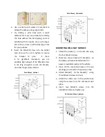
Flat Surface Mount _Top


STEP  5:  CONNECT  THE  POWER 

SOURCE


The  standard  power  supply  of  the  ZLF-372  is 

9V-36V  DC.  Please  use  the  factory  supplied 

power  cable.  Refer  the  below  wiring  diagram  

to  connect  each  wire  to  power  source  of  the 

vehicle. 

Power Cord


Power Wiring Diagram


When you power cord is connected the ZLF-372 

and the power source, watch for the power LED 
to illuminate. 


STEP 6: CONNECT THE AP TO YOUR 

PC


To  configure  the  ZLF-372  as  FAT  AP,  please  do 

the following: 

1.


Insert  one  end  of  an  Ethernet  cable  to  the 

Ethernet port on the ZLF-372. 

2.


Insert  the  other  end  to  the  LAN  port  on 
your PC. 

3.


From your computer, go to Start > Settings > 

Network  Connections  or  Start  >  Control 
Panel > Network Connections. 

4.


When   the   Network   Connections window 

N

ote: 

If the AP is deployed with an AP controller, 

please skip 

STEP 6

STEP 7 

and 

STEP 8 

and go to 

STEP 9 

to proceed. 

Wire Colors


Description


Red 

Connect to battery po 

Black 

Connect to battery negative - 

Orange 

Connect to ACC ignition 

Brown 

Connect to relay control line 


Summary of Contents for ZLF-372

Page 1: ...bed in this guide you will be able to place the AP at your site and provide wireless network access tousers PACKAGE CONTENTS ZLF 372 Power Cable Mounting Kit Security Plate CableCover Screw Kit LTE GPS Antennas HARDWAREOVERVIEW 3D View Bottom View No Item 1 Power 2 LEDIndicators 3 Console Port 4 LTE Antennas Side View No Item 1 RF 45 Ethernet Port 2 GPS Antenna 3 SIM Card Slot 4 Reset Pinhole ...

Page 2: ...etails about selecting a data plan and about the process for provisioning your SIM Once you have an activated SIM Mini SIM insert it into the SIM slot of ZLF 372 Be sure to insert the card with the notch end first and the gold contacts facing down it will click into place To protect the SIM card from theft you can attach the anti theft security plate to cover the SIM card slot 1 Clear cutouts on t...

Page 3: ...LF 372 LTE Antenna Installation GPS AntennaInstallation 2 Position the antennas so they suit your deployment scenario STEP 3 ATTACH THE CABLE COVER The ZLF 372 comes with a plastic cable cover to hide AP s power and antenna connectors to prevent removal of power and antenna cables 1 Clear cutouts on both sides of cable cover marked in red 2 Route the antenna and power cables out of the access slot...

Page 4: ...ach the access point to any pole from 29 to 33 mm in diameter 2 The pole mount kit contains several parts that you must assemble prior to mounting on a pole First you need to attach the bracket on the ZLF 372 using the four M5xL10 screws 3 Attach bracket on the bracket using three M5xL10 screws and nuts 4 Attach the mounting bracket with ZLF 372 on the pole using bracket and four M5xL20 bolts with...

Page 5: ...enough If the M5xL40 screw is not long enough to secure the bracket use other longer screw instead Pole Mount_Vertical Pole Mount_Horizontal MOUNTING ON A FLAT SURFACE 1 Attach the bracket on the ZLF 372 using the four M5xL10 screws 2 Mark two screw holes with bracket on the place you have selected where the power is available nearby on thevehicle 3 Use a drill to create two holes on the two marki...

Page 6: ...UR PC To configure the ZLF 372 as FAT AP please do the following 1 Insert one end of an Ethernet cable to the Ethernet port on the ZLF 372 2 Insert the other end to the LAN port on your PC 3 From your computer go to Start Settings Network Connections or Start Control Panel NetworkConnections 4 When the Network Connections window Note If the AP is deployed with an AP controller please skip STEP 6 S...

Page 7: ...C to enter the values manually Click Apply to save changes 4 Go to RF Configure Wireless Settings For dual band 5G setting select Card 2 first then go to RF Configure Wireless Settings 5 Select your location from Country Region Click Apply to save the changes 6 Select a clean channel 7 Go to RF Configure SecurityProfile 8 Select a profile eg 1 then click Edit 9 Type the name of the network in the ...

Reviews: