ZPrinter
®
450 Hardware Manual
Setup And Print The Build
21
All Rights Reserved
10/2/07
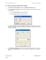
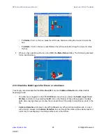
2. Select
Edit > Make Fixture
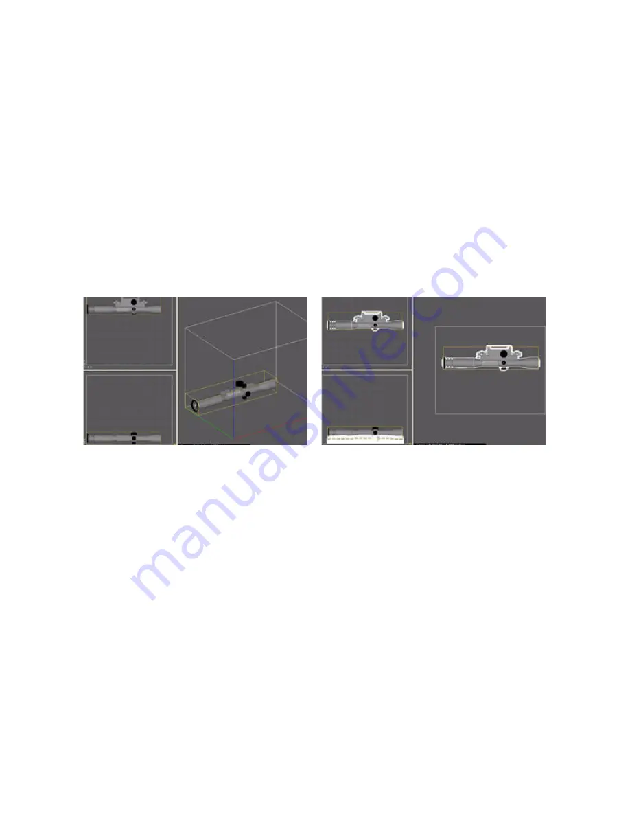
. ZPrint orients the part in the 3D View for building the Fixture.
NOTE:
The settings in the
Make Fixture
dialog are the
General Preference
settings that are pre-
set in the software and the recommended settings for the printer. See the
for a description of the
Make Fixture
dialog should you need to change any of these settings.
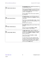
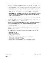
3. There are two features you may choose to enable for a Fixture:
•
Make Bumper:
To add a bumper to a fixture, check the
Make Bumper
checkbox. A bumper
will be generated on the Fixture base.
•
Holes between walls:
Powder may get trapped between the Fixture and the part. You can
generate a Fixture with holes at the grid intersections to allow powder to escape during auto-
matic powder removal. A zero (0) in this field means no holes are generated on the Fixture.
The higher the percentage, the larger the holes will be on the Fixture.
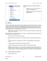
4. Click
OK
. The Fixture is generated.
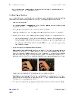
5. Select
View > Collision Detection
to ensure the Fixture is not touching the part. If the Fixture is
touching the part, do the following:
•
Select the fixture and press
Delete
on your keyboard.
•
Open the
Make Fixture
dialog and increase the
Accuracy Coefficient
value by 1 (one).
•
Click
OK
to regenerate the Fixture.
•
Run
Collision Detection
again.
2.9.2
Create a Fixture for a portion of a part:
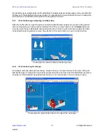
1. Select the part in ZPrint. ZPrint orients the part in the 3D View for building the Fixture.
2. Select
Edit > Make Fixture
.
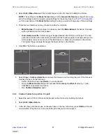
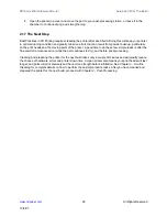
3. In the 3D View, point the mouse on the wire frame in the top, left corner, press
Shift
and the left
mouse button. Drag the box to an area of the part that you want to support.

