background image


 Z-3100 Service Guide  

6 / 8

S

ERVICE  

G

UIDE

Take Apart 
Before You Start 

Important Instructions 


Read these instructions completely before you begin. 


Follow all instructions. 


Heed all warnings. 


Tools to Prepare 

 Philips 

screwdriver. 

 
Please follow these steps to take apart Z-3100. 
 
1. 

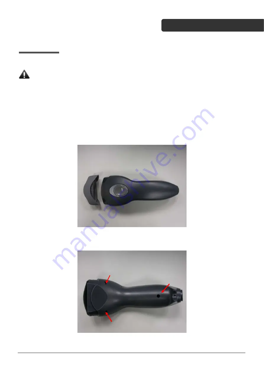
Remove the front cover of the scanner. 


2. 

Remove the screws as pointed in red arrows using a screwdriver. 


Summary of Contents for Z-3100

Page 1: ...elow Version Date Description of Version 1 1 Aug 19 2010 Initial release 1 2 Dec 16 2010 Corrected P N for top and bottom case white FCC cable and scan engine 1 3 July 05 2012 Updated scanner covers 1...

Page 2: ...l it may cause interference to radio communications The equipment has been tested and found to comply with the limits for a Class A computing device pursuant to EN55022 and 47 CFR Part 2 and Part 15 o...

Page 3: ...UIDE Table of Contents Preface 2 Important Notice 2 Radio Notice 2 Radio and Television Interference 2 For CE Countries 2 Table of Contents 3 Scanner Parts 4 Take Apart 6 Before You Start 6 Important...

Page 4: ...f tapping screw M1 2 3 5mm round Philips head pointed 2 3 684 100000 391 Dust Cover 1 4 863 100012 601 Scan engine 1 5 613 000004 202 Engine board 1 6 031 006010 520 031 006010 600 White FFC cable 1 7...

Page 5: ...oard assembly 1 8 031 006010 520 FFC cable 1 9 640 031000 001 Double sided tape 1 10 521 202000 4R0 Self tapping screw M1 6 4 0mm flat head 6 11 521 113000 5R0 Self tapping screw M2 5 0mm square head...

Page 6: ...ons Read these instructions completely before you begin Follow all instructions Heed all warnings Tools to Prepare Philips screwdriver Please follow these steps to take apart Z 3100 1 Remove the front...

Page 7: ...Z 3100 Service Guide 7 8 SERVICE GUIDE 3 Remove the top case and the dust cover 4 Remove the screws from trigger 5 Remove the trigger and the top case...

Page 8: ...Z 3100 Service Guide 8 8 SERVICE GUIDE 6 Remove the white FFC cable from the bottom case as marked in red 7 Remove the screws as marked in red 8 Separate the boards from the bottom case...

Reviews: