background image

Z-6070 

Hands-Free Dual-Laser Omnidirectional Scanner


Service Guide 

 
Revision History 


Changes to the original manual are listed below: 

Version Date 

Description 

of 

Version 

1.0 

Sept. 2, 2010 

Initial release 

2.0 

Aug 5, 2013 

Updated to new parts and procedures 

Summary of Contents for Z-6070 Series

Page 1: ...ser Omnidirectional Scanner Service Guide Revision History Changes to the original manual are listed below Version Date Description of Version 1 0 Sept 2 2010 Initial release 2 0 Aug 5 2013 Updated to...

Page 2: ...he user should consult the manufacturer an authorized dealer or experienced radio television technician for additional suggestion The user may find the following booklet prepared by the Federal Commun...

Page 3: ...ble of Contents Preface 2 Important Notice 2 Table of Contents 3 Introduction 4 Product Overview 4 Scanner Parts 6 Take Apart 7 Before You Start 7 Important Instructions 7 Tools to Prepare 7 Z 6070 Se...

Page 4: ...n customer transaction time Its broad scan field could effectively facilitate scanning barcodes on products in all kinds of shapes Moreover it is designed for both hands free and handheld applications...

Page 5: ...tting in the adjustable stand press down this button for 5 seconds and it will automatically change the beeper volume LED A red LED indicates the scanner is ready to read a barcode while a green LED i...

Page 6: ...over 1 560 060700 561 Decorative panel 4 560 060700 562 Decorative panel black 1 560 060700 571 Front case frame 5 560 060700 572 Front case frame black 1 6 866 070000 514 Center mirror base assembly...

Page 7: ...mpletely before you begin Follow all instructions Heed all warnings Tools to Prepare Philips screwdriver Please follow these steps to take apart Z 6070 1 Remove the 4 screws 521 014000 020 from the ba...

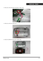
Page 8: ...SERVICE GUIDE 3 Remove the connector from the main board circled in red 4 Remove the connector circled in red 5 Remove the 4Pin Pitch 1 0mm Wire to Board cable Z 6070 Service Guide 8 10...

Page 9: ...ed in red from the back case and remove the screw pointed by red arrow 521 003000 8R0 7 Remove the decorative panel from the back case 8 Remove the 4 Shock absorbing rubbers and the 4 screws 521 00B00...

Page 10: ...Z 6070 Service Guide 10 10 SERVICE GUIDE 9 Separate the front case dust cover front case frame shock absortbing rubbers and the screws...

Reviews: