background image


Omnidirectional In-Counter Scanner 

7

U

SER

M

ANUAL

Connection  

Connecting Power 

The power supply pr12 volts, -12 volts and +5 volts DC voltage to the scanner; 
the detailed power requirement is as below:   
 

Voltage AC100~240 
Frequency  

50~60HZ 

Current (RMS) 

600mA 

5V,+12V,-12V 

 
A power cord is required to connect the electrical outlet and power supply. Select the 
proper IEC power cord for your country. To connect an external power to the scanner, 
plug the power supply into the power jack on the scanner and then plug the power 
supply into an AC outlet. Blue LED would light when the scanner is powered and ready to 
scan.  
 
The scanner turns on when the AC power is supplied, and turns off when the power is 
removed. There is no on/off switch on the scanner itself. 
 
Use only an AC/DC power supply approved for the scanner. Use of other power supplies 
may cause damage to the product, and void the factory warranty. You must verify that 
the power source will supply “clean” electrical power to the equipment; that is, it must 
be free of excess electrical noise. 


Verifying Scanner Operation 

Before connecting the scanner to host or mounting to counter, you may follow the 
procedure below to verify scanning operation.   
 
1.


Insert the 10-pin modular plug of the interface cable into the “Host” connector on 
the scanner until a firm click is heard. 

2.


Plug the other end of the cable to the host. 

3.


Power up the scanner. The speaker would sound four beeps and the two LED 
indicators glow blue to indicate good self test. The scanner is ready to work. 

4.


Present a known-good test barcode to the scanner. The scanner should issue a short 
beep and the LED should flash red momentarily.   


Summary of Contents for Z-6180

Page 1: ...Omnidirectional In Counter Scanner 1...

Page 2: ......

Page 3: ...vision History Changes to the original manual are listed below Version Date Description of Version 1 0 July 20 2010 Initial release 1 1 March 21 2011 Added EAS connection 1 2 March 27 2012 Corrected d...

Page 4: ...r language in any form or by any means electronic mechanical magnetic optical chemical manual or otherwise without express written consent and authorization We have taken reasonable measures to provid...

Page 5: ...ct A failure of the scanner motor while the laser diode continues to emit a laser beam may cause emission levels to exceed those for safe operation The scanner has safeguards to prevent this occurrenc...

Page 6: ...canner to the Counter 12 Shelf Mounting 13 Horizontal Flush Mounting 14 Vertical Flush Mounting 18 Auxiliary Handheld Scanner Connection 18 Connecting EAS System 20 Window Glass Replacement 23 Set Up...

Page 7: ...second The scanner also includes a scratch resistant window to withstand the wear and tear daily usage Should the window ever need to be replaced it is serviceable in the field reducing downtime and p...

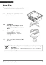
Page 8: ...le This cable is usually but not always supplied Model depends on customer needs 1 ea Power supply power cord Model depends on electrical requirements of your geographic location 1 ea User s manual pr...

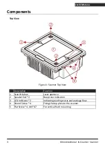
Page 9: ...ure 1 Scanner Top View Description Function 1 Scan Window Laser aperture 2 Speaker Exit 2 Beep tone indication 3 LED Indicator 2 Indicating reading status and package flow 4 Round Screw 4 Fixing the t...

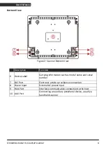
Page 10: ...ion 6 Device Label Carrying information such as model name and serial number 7 EAS Port Electronic article surveillance connection 8 Power Input External AC power input 9 Host Port Interface communica...

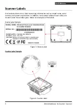
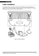
Page 11: ...s a label containing information such as model name serial number and power requirement In addition two caution labels of laser safety are located under the window glass Below are examples of the labe...

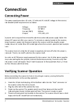
Page 12: ...stallation The scanner is to be connected to a host e g POS with the use of external power required The scanner also supports an auxiliary scanner and EAS application The figure below gives you an ove...

Page 13: ...off switch on the scanner itself Use only an AC DC power supply approved for the scanner Use of other power supplies may cause damage to the product and void the factory warranty You must verify that...

Page 14: ...ting to the Host The interface cable comes with different host end connectors depending on the host Follow the steps below to connect the device to the host 1 Turn off the host system 2 Connect the sc...

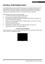
Page 15: ...ce cable 1 Turn off the host system and power off the scanner 2 Disconnect the old interface cable from the host 3 Press down the small tab on the connector where the old cable is attached to the scan...

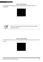
Page 16: ...e allows setting as keyboard wedge interface for IBM PC AT PS 2 and compatibles Cover the unwanted barcode to ensure that the scanner read the desired barcode only Return to RS 232 default The RS 232C...

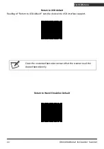
Page 17: ...r 11 USER S MANUAL Return to USB default Reading of Return to USB default sets the device into USB interface support Cover the unwanted barcode to ensure that the scanner read the desired barcode only...

Page 18: ...ensure mounting stability avoid placing the scanner in such a way as to subject it to excess vibration bumping spilled liquid etc The scanner should be installed in a location away from direct sunlig...

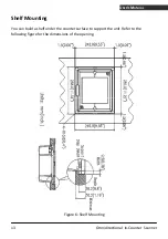
Page 19: ...onal In Counter Scanner 13 USER S MANUAL Shelf Mounting You can build a shelf under the counter surface to support the unit Refer to the following figure for the dimensions of the opening Figure 6 She...

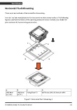
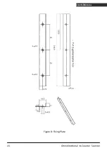
Page 20: ...You can use two metal plates to fix the scanner to the counter surface The following figures specify dimensions of the opening plate and screw Contact your dealer for procurement of the mounting acces...

Page 21: ...Omnidirectional In Counter Scanner 15 USER S MANUAL Figure 8 Fixing Plate...

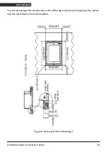
Page 22: ...tional In Counter Scanner 16 USER S MANUAL You can also design the counter top as the following structure and simply put the device into the desired position without plates Figure 9 Horizontal Flush M...

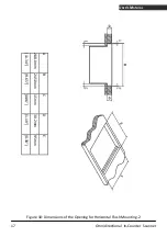
Page 23: ...Omnidirectional In Counter Scanner 17 USER S MANUAL 11 34 288 0mm A 9 65 245 0mm B 0 06 1 5mm C 1 19 30 2mm D 0 38 9 5mm E Figure 10 Dimensions of the Opening for Horizontal Flush Mounting 2...

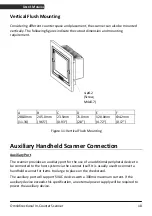
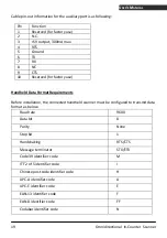
Page 24: ...2 8 4 72 0 17 Figure 11 Vertical Flush Mounting Auxiliary Handheld Scanner Connection Auxiliary Port The scanner provides an auxiliary port for the use of an additional peripheral device to be connect...

Page 25: ...Handheld Data Format Requirements Before installation the connected handheld scanner must be configured to transmit data format as below Baud rate 9600 Data bit 8 Parity None Stop bit 1 Handshaking R...

Page 26: ...ld scanner data format as above table requirements 2 Turn off the host system 3 Connect the handheld scanner to the auxiliary port using the auxiliary cable 4 Connect the external power supply for the...

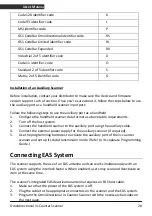
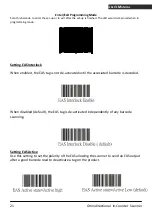
Page 27: ...n programming mode etting EAS Interlock S S tag is not de activated until the associated barcode is decoded hen disabled default the EAS tag is de activated independently of any barcode etting EAS Act...

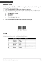
Page 28: ...settings AS Port Use this setting to set re 1 Scan the Enter Exit Programming barcode to begin the setup 2 Scan 3 ASCII number barcodes Ple millisecond For example 000 disable the feature 001 10 msec...

Page 29: ...because different glass types have different levels of transmittance When window glass change is required it is recommended to change glass of the same type If window type needs to change the scanner...

Page 30: ...Put the top plate back to the device and tighten the four round screws Front Cover Seal Rubber Glass Holder 8 Screws To protect the window glass it suggested leave those heavy bulky products in the ca...

Page 31: ...at any time without affecting the other parameters Power Up Self Test The scanner would automatically run the self test when the power is supplied It is to verify that the scanner and interface are f...

Page 32: ...as it accepts each code For some parameter setting such as barcode length and identifier code it is required to scan the Set barcode to save the configuration When done again present the Enter Exit P...

Page 33: ...byte commands to the scanner The default settings of the commands are as follows ASCII Code Function Byte is Also Called 0E Hex enable resumes disable Shift Out or Ctrl N 0F Hex disable Shift In or Ct...

Page 34: ...ates the scanner has a motor or laser failure For motor failure a periodic beep is sounded In this case return the unit for repair Flashing red light The scanner is programmed in USB interface but not...

Page 35: ...tching off after 10 minutes the second step is the motor switching off after 30 minutes The time period is programmable The scanner has two IR sensors that detect activity in front of the scan window...

Page 36: ...pattern The scan volume extends approximately 20cm 8 in front of the scan window Barcodes are most effortlessly scanned when swept through the scan volume from the scan window On the other hand the t...

Page 37: ...picking them up Figure 14 1 Scanning Mode Sliding Sweeping mode Users sweep items through the scan volume Left to right or right to left are both okay Figure 14 2 Scanning Mode Sweeping Presentation...

Page 38: ...order to remove dirt and fingerprints It can be cleaned while the scanner is running When cleaning wipe the scan window with a soft lint free cloth and a non abrasive cleaner to avoid scratching and d...

Page 39: ...oes self test when powered up The red and blue LED would both light on appearing the color purple when the scanner fails the self test When it happens disconnect the scanner from its power source imme...

Page 40: ...ime System Interfaces IBM 46xx keyboard wedge OEM IBM USB RS 232C HID USB USB virtual COM Physical Height 103 mm Depth 242 mm Width 285 mm Weight 3 000 g without cable and power supply Cable Standard...

Page 41: ...Omnidirectional In Counter Scanner 35 USER S MANUAL Dimension Unit mm inch Figure 15 Dimension...

Page 42: ...level N C N C 6 N C RXD RS232 level N C N C 7 Keyboard_ Clock N C N C IBM_B 8 PC 5V N C USB 5V N C 9 PC_ Data N C N C IBM_ A 10 N C TXD RS232 level N C N C Auxiliary Port RS 232 IN Only Pin Function...

Page 43: ...DIN F Din Din Din Din 1 PC Data 1 KB Data 2 N C 2 N C 3 GND 3 GND 4 PC 5V 4 PC 5V 5 PC Clock 5 KB Clock 6 N C 6 N C RS 232C Cable DTE Pin Out DB 9 F FUNCTIO N 2 TX 3 RX 7 CTS 8 RTS 5 GND RS 232C Cabl...

Page 44: ...y Handheld Scanner 18 Counter Installation 12 Horizontal Flush Mounting 14 Pre Installation Considerations 12 Shelf Mounting 13 Vertical Flush Mounting 18 Window Glass Replacement 23 L LED Indications...

Reviews: