Introduction
This Quick Guide applies to the Advanced Compact Dual-Laser Omnidirectional Vertical
Scanner. Detailed information about installation, troubleshooting and configuration can be
found in the User’s Manual and Programming Guide in the CD-ROM.
We reserve the right to make changes to improve reliability, function or design. For the latest
revision of the manual please contact your distributor.
Unpacking
The scanner package may be altered upon customer request but it usually contains
- 1 ea. scanner
- 1 ea. Interface cable
- 1 ea. 9V power adaptor, and
- 1 ea. manual in CD-ROM or hard copy
Installation
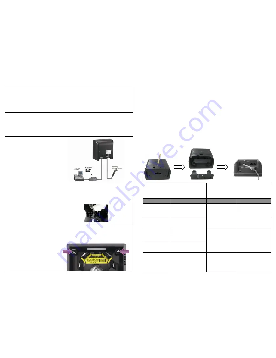
The scanner is to be connected to a
host (e.g. POS). This figure gives you
an overview of the cable installation.
Power
The scanner requires a minimum of
450mA at 9V DC power and the use of
external power is usually
recommended. It turns on when power
is supplied and turns off when power is
removed. There is no on/off switch on
the scanner itself.
Cable Replacement
The interface cable comes with
different host-end connectors and the
cable is attached to the scanner with a
10-pin modular connector. When
properly seated, the scanner is secured
in the scanner bottom by a flexible
retention tab. The cable is designed to
be field replaceable. Replacement
cables can be obtained from your
authorized distributor.
Mounting Plate Installation
When installing the host cable to the mounting plate,
please insert the flat side of the cable bracket in the
cable release hole first as shown in illustration.
Tone and Volume Adjustment
The tone and volume can be changed by using the touch control sensors in the front. There are
three tones/levels of volumes to choose from. Gently touch the sensor and the scanner would
change to its next tone/volume level. Repeat touching till the desired sound is heard.
However, the volume setting is saved in
volatile memory. That means the
change will lost when the scanner
powers down. On next power-up the
scanner would reset to the configured
setting. If you wish to keep the changed
volume setting, use the Programming
Guide to set and save the changes.
Verifying Scanner Operation
Before mounting your scanner, please follow the procedure below to verify scanning operation.
1. Take a stick to poke in the hole on the back of the scanner to remove the mounting plate.
2. Insert the interface cable into the “Host” connector at the back of the scanner until a firm
click is heard.
3. Put the mounting plate back (optional).
4. Plug the other end of the cable to the host.
5. Plug the power adapter into the jack on the interface cable.
6. Plug the AC end of the power adapter into an AC outlet. The scanner powers up, the
speaker sounds four beeps and the LED indicator glows blue.
7. Present a known-good test barcode to the scanner. The scanner should issue a short beep
and the LED should flash red once.
The scanner should read one barcode, beep, and the LED remain red if it is connected to
a keyboard wedge but not connected to a live host terminal.
The LED would flash red and read no barcode if the scanner is programmed in USB
interface but not connected to a host device.
LED Indications
There are red and blue dual color LED
indications on the head of the device indicating
the operational status of the scanner.
Sound Indications
The device uses a speaker to give audio
feedback on scanner operation. The following
are the sound indications.
LED Status
Indication
Beeps
Indication
LED off
No power supplied to the
scanner.
One beep
A barcode has been
successfully decoded.
Steady blue light
The scanner is powered
on and ready to scan.
Two beeps: low-high
The scanner has entered
programming mode.
One red flash
A barcode has been
successfully decoded.
Two beeps of the
same tone
Scanner has returned
from programming to
normal mode.
Steady red light
The scanner is in
programming mode.
Flashing blue light
The scanner is in sleep
mode.
Steady red/blue
light
The scanner has a motor
or laser failure. Return
the unit for repair.
Four beeps in series
continuous tone
This indicates the
scanner passed self-test
when powered on and is
operating properly.
Flashing red light
The scanner is
programmed in USB
interface but not
connected to a host
device.
Continuous tone
This is a failure
indication.
Return the unit for repair.


