background image

zebris Medical GmbH 

PDM/PDM mobile Technical Data and Operating Instructions 

Page 21/42 


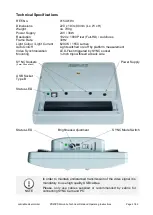
Technical Specifications 

REF-No. 

01540194 

Dimensions 

220 x 183 x 80mm (L x W x H) 

Weight 

ca. 790g 

Power Supply 

24V / 36W 

Resolution 

1920 x 1080 Pixel (Full-HD) / Autofocus 

Frame Rate 

30Hz 

Light Colour / Light Current  

6200 K / 1550 Lumen 

Auto On/Off 

Light switched on-/off by platform measurement 

Video Synchronization 

LED-Flash triggered by SYNC socket 

Mounting 

¼ Inch tripod-thread at back side 


NOTE 

In order to maintain undisturbed transmission of the video signal it is 
mandatory to use high quality USB cables. 

Please,  only  use  cables  supplied  or  recommended  by  zebris  for 
connecting SYNCCam and PC. 


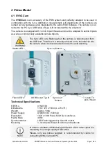
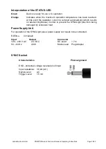
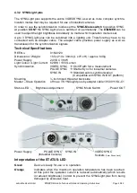
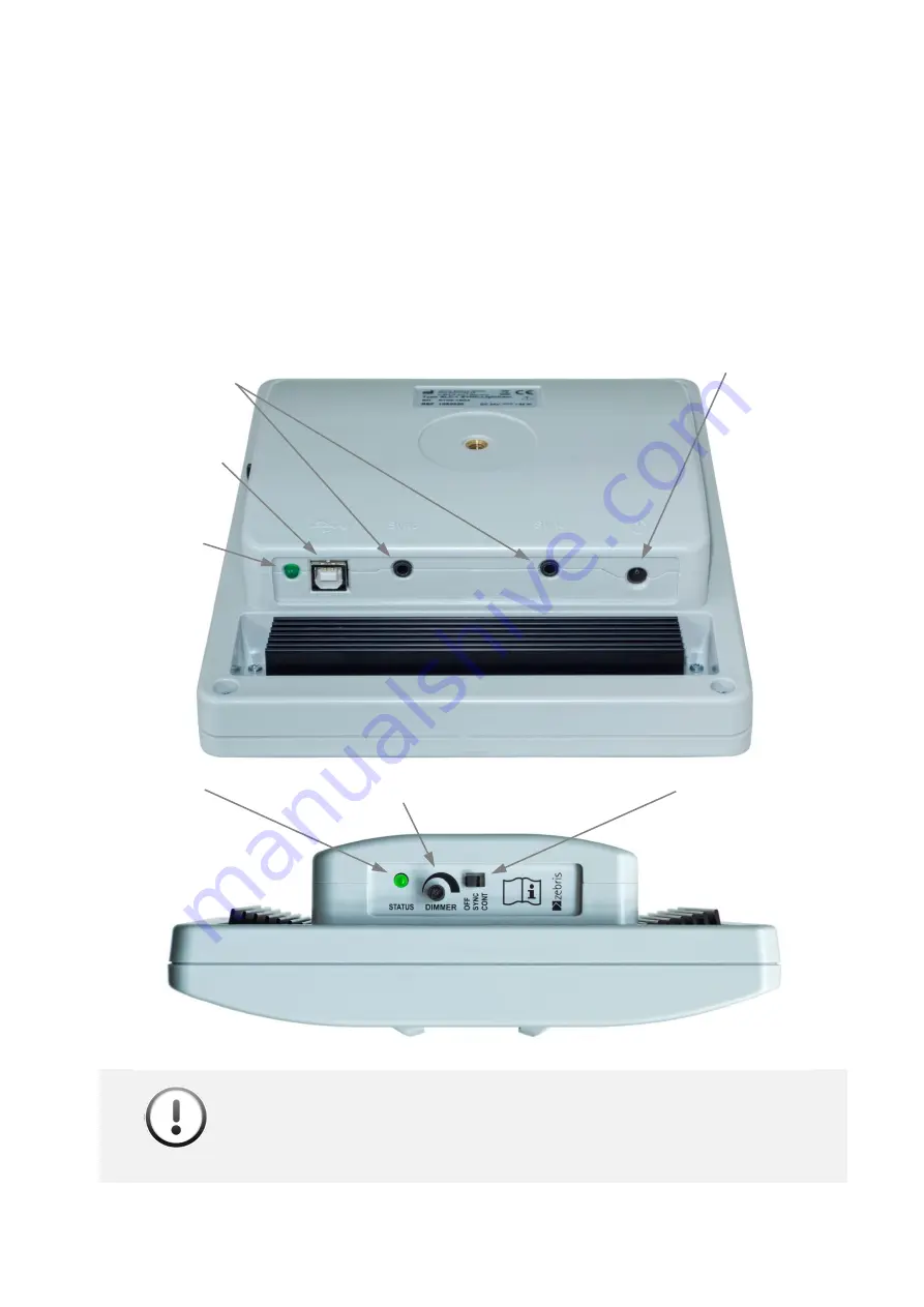
Status-LED 

Brightness Adjustment 


SYNC Mode Switch 

SYNC Sockets  

(3 mm Phone Jack)


Status-LED 

Power Supply 

USB Socket 
Type B 


Summary of Contents for PDM

Page 1: ...zebris Medical GmbH REF 79010135 Text Release 03 01 2019 Measuring System for Pressure Distribution Measurement PDM PDM mobile Specifications and Operating Instructions...

Page 2: ...HTCAM 20 4 3 LED VIDEO LIGHTS SYNCLIGHT SYNCLIGHT PLUS 23 4 3 1 SYNCLight 24 4 3 2 SYNCLight plus 25 4 3 3 Power Supply Unit SYNCLights 26 4 4 REPLACEMENT PARTS PDM SYSTEM 28 4 5 ACCESSOIRES PDM SYSTE...

Page 3: ...bH PDM PDM mobile Technical Data and Operating Instructions Page 3 42 6 4 CLEANING AND DISINFECTION 41 6 4 1 Cleaning 41 6 4 2 Manual Disinfection 41 6 5 DISPOSAL 42 6 5 1 Packaging 42 6 5 2 Disposal...

Page 4: ...9726 0 Am Galgenb hl 14 Fax 49 0 7562 9726 50 88316 Isny im Allg u E Mail info zebris de Germany Web www zebris de Sales Support zebris Medical GmbH Phone 49 0 7562 9726 300 Am Galgenb hl 14 Fax 49 0...

Page 5: ...er manual for the zebris FDM application software Part 3 User manual of the accessories like e g projector or PC NOTE Please closely observe the user manuals with initial operation use or maintenance...

Page 6: ...ntial risk which could lead to damaging of the device These NOTE symbols describe the risks involved and how those can be avoided CE mark according to EC Directives 2014 30 EEC and 2014 35 EEC Low Vol...

Page 7: ...uids Liquids entering the device can cause fire electrical shock or other severe accidents The PDM system is NOT specified for the operation in vacuum hy perbaric or altitude chambers The measuring sy...

Page 8: ...e safety reliability and performance of the components delivered by zebris re sponsibility is assumed if Assembly extensions re settings changes or repairs were carried out through zebris or third par...

Page 9: ...r must always be contacted in all cases of fault or doubt If any fluids should penetrate the device it is mandatory for the device to undergo a technical safety test Damaged plug connectors and leads...

Page 10: ...size of the measuring area the number of single sensors included in the sensor module and the supported sampling fre quency All other technical data is identical Interfaces USB Bluetooth optional Syn...

Page 11: ...ace L x B 406 x 339 mm 406 x 339 mm Resolution Inch 1 4 Sensors cm Inch 1 4 Sensors cm PC Interface USB 2 0 USB 2 0 Bluetooth Type PDM S PDM S mobile REF Nr 01233020 01233020 Dimensions L x B x H 710...

Page 12: ...370 x 535 x 15 mm 1370 x 535 x 15 mm Weight 11 4 kg 11 5 kg Measuring frequency 120 Hz 120 Hz Number of sensors Columns x Lines 8046 56 x 144 8046 56 x 144 Sensor surface L x B 1220 x 474 mm L x B 122...

Page 13: ...ions between platform and PC will be established by the connector box located at the bottom of the platform Battery Switch SYNC Video USB Socket mini B Power Supply Status Indicator LED Infrared Inter...

Page 14: ...Indicator flashes on Platform ready for measurement NO USB connection with PC on on Platform ready for measurement USB connection with PC established Yellow Battery Charging PDM mobile only flashes o...

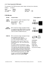
Page 15: ...ctions Page 15 42 3 5 zebris SYNC The zebris SYNC is the standard solution for the synchronization of the PDM System with zebris camera and lighting systems 3 5 1 Specification SYNC Interface Connecti...

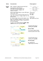
Page 16: ...nnection of SYNCCam or SYNCLightCam the Video Sync Control Cable is required REF No 21030316 Video Sync Control Cable cable length 5 Video SYNC Signal Direction Output from platform to connected devic...

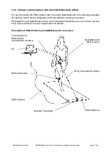
Page 17: ...R interface which can be integrated within the platform housing is required PDM platform and DAB Bluetooth are synchronized automatically as soon as both devices have been switched on and a measuremen...

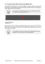
Page 18: ...tegrated in the housing at the end of each platform NOTE For connection arrange both platforms a shown in the picture below The front ends must point the outer side Both platforms must be connected to...

Page 19: ...e Sync LEDs are flashing when the camera is disconnected from the USB port Therefore it is strongly advised not to look directly into the camera when it is disconnected in order to avoid dazzling Tech...

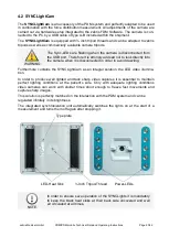
Page 20: ...camera when it is disconnected in order to avoid dazzling Furthermore contains the SYNCLightCam as an integral solution the LED video illumina tion In order to produce well lighted and tack sharp vid...

Page 21: ...0 K 1550 Lumen Auto On Off Light switched on off by platform measurement Video Synchronization LED Flash triggered by SYNC socket Mounting Inch tripod thread at back side NOTE In order to maintain und...

Page 22: ...ed automatically which results in reduced brightness in order to prevent the SYNCLight plus from being damaged by excessive heat Power Supply Unit For operation of the SYNCLight plus a power supply un...

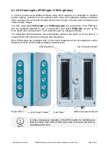
Page 23: ...and perfectly adapted for use in combination with zebris SYNCCam as well as the force distribution measurement Their brightness can be adjusted infinitely The integrated synchronization unit automati...

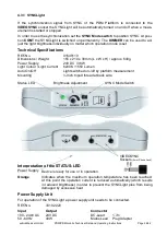
Page 24: ...8mm L x W x H approx 640g Power Supply 24V DC 36W Light Colour Light Current 6200K 1550 Lumen Auto On Off Light switched on off by platform measurement Mounting Inch tripod thread at back side Interpr...

Page 25: ...al Specifications REF No 01540120 Dimensions Weight 155 x 210 x 38mm L x W x H approx 640g Power Supply 24V DC 36W Light Colour Light Current 6200K 1550 Lumen Synchronization VIDEO SYNC On Off with fo...

Page 26: ...d to VIDEO SYNC OUT and can be used for control of additional devices SYNC IN ESD protected voltage reversal proof input Input resistance 38K Pull Up VIH High Level Input Voltage 3 7V VIL Low Level In...

Page 27: ...e PULSE SYNC By utilizing pulsed light optimal lighting condi tions for industrial cameras can be accom plished without being too bright or disturbing for the human eyesight In order to use PULSE SYNC...

Page 28: ...10 32 64 Bit 79010100 Hardware User Manual English version Please contact zebris support for free PDF version Print version is liable to be charged 79010181 User Manual zebris FDM Software English ver...

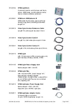
Page 29: ...5m both sides phone jack 3 5mm 01830041 Video Sync Control Cable 2 5 Length 2 5m both sides phone jack 3 5mm 01540110 SYNCLight with 10 high power LEDs power supply unit light intensity infinitely va...

Page 30: ...Do not set up the platform near a source of heating or in direct sunlight in front of a window as a rise in temperature can lead to inaccurate measuring results Set up the measuring system in a way th...

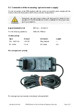
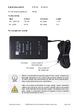
Page 31: ...cket in the connector compartment WARNING Exclusively use the power supply unit approved by zebris for the operation of the PDM platform which is suitable for the power sup ply of your platform Netzte...

Page 32: ...the type plate indications of the power supply and the platform in terms of mains voltage and mains frequency with the local characteristics Only connect when they are in accordance WARNING Carry out...

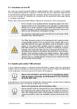
Page 33: ...r third parties If the zebris FDM software shall be installed in a net work data network the operator is obliged to determine analyse evaluate and control the risks that are connected with doing so pa...

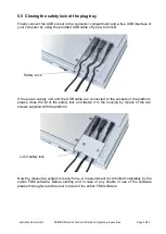
Page 34: ...i B If the power supply unit and the USB cable are connected to the sockets of the platform please close the lid of the safety lock and fasten it to the housing by means of the two screws supplied wit...

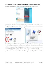
Page 35: ...nd added to the Bluetooth capable systems When clicking on the PDM mobile symbol it is highlighted Click on the symbol again with the left mouse button and select Settings under the section Services s...

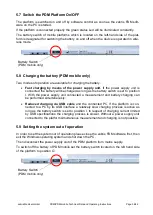
Page 36: ...to position I With the power supply unit connected a measurement and battery charging can be performed simultaneously Reduced charging via USB cable and the connected PC If the platform is con nected...

Page 37: ...sensor area by the first step and moves on This kind of measurement guaranties reproducible steps and results Notice These results differ more or less from these by normal walking 5 10 2 Data recordin...

Page 38: ...arting any maintenance work 6 1 Mandatory periodic inspections For maintaining the correct state of the electrical equipment checks and technical safety inspections have to be carried out repeatedly e...

Page 39: ...ns These include above all line or column shaped meas uring patterns deviating from the surrounding values Whenever faults occur or in case of doubt the manufacturer or sales partner authorized by zeb...

Page 40: ...le in case of malfunction of your PDM measuring system our service employees need the following information Device type serial number of the PDM platform Serial number is located on the type plate on...

Page 41: ...infection liquid WARNING No spray disinfection Spray disinfection can destroy the highly precise measurement sensors of the platform Recommended disinfection agent Composition approx 25 ethanol 35 Pro...

Page 42: ...sal is carried out by the manufacturer For this purpose the system should be shipped to the manufacturer and will be forwarded to regular disposal by zebris The improper interaction with electronic wa...

Reviews: