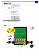
background image

22


GB

POWER CONNECTION

 ZD 20

 (Fig. 

5

)

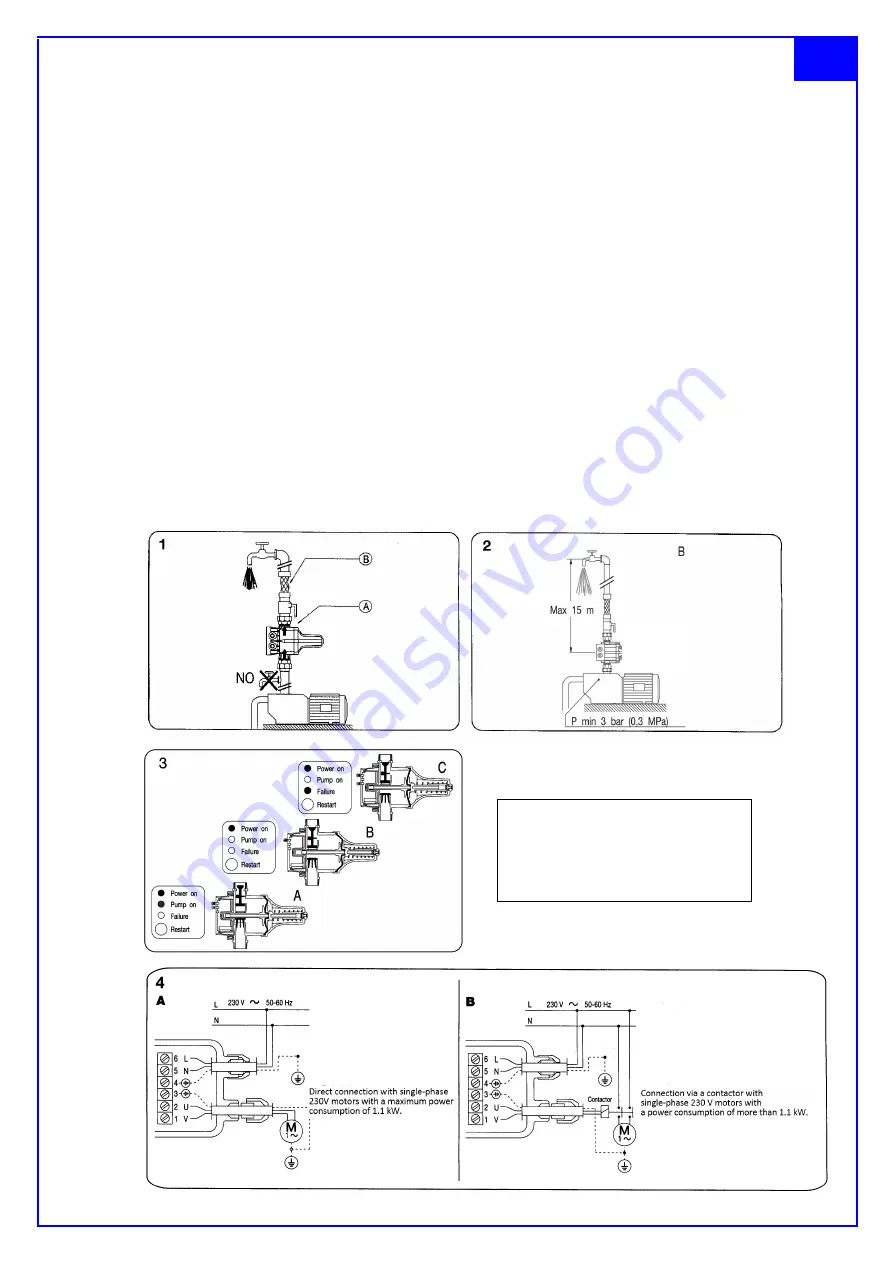
The electrical connection must be made by qualified personnel in accordance with applicable legislation. The device must always be 

preceded by an all-pole switch with a contact distance of at least 3 mm. Single-phase pumps (230 V) with a motor power of up to 2.2 

kW (3 HP) (Fig. 4 / A) can be connected directly to the unit, while single-phase pumps with a capacity of more than 2.2 kW (3 HP) 

(Fig. 4 / B) must be connected to the device via a contactor. Check the mains voltage and the data indicated on the nameplate of the 

pump motor.

Run the power supply as shown in the diagrams in Fig. 

5

.

Use HOS or H07 cables with a cross-section of 3x1.5 mm².

Make sure that the device is connected to the grounding system.

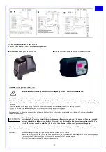
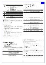
COMMISSIONING AND OPERATION (Fig. 3)

The green "Power on" light on the front panel of the unit indicates voltage is present while a yellow "Pump on" lamp indicates that the 

pump is operating. When the unit is plugged in, the green and yellow lights will turn on. the yellow light indicates that the pump has 

started (Fig. 3 / A); it remains in operation for a few seconds to pressurize the system. If this time is not sufficient, the red light comes 

on,  in  this  case  hold  down  the  red  button  Restart  and  wait  until  water  comes  out  of  an  opened  sampling  point.  After  closing  the 

sampling point, the device switches off the pump and then remains in standby mode; the green light stays on and the device is ready 

to carry out all further command and control steps in complete autonomy (Fig. 3 / B). When opening a sampling point, the device 

switches on the pump; This remains in operation until the sampling point is closed again (Fig. 3 / A). After closing the sampling point, 

the device restores the maximum pressure in the system, switches off the pump and returns to standby mode (Fig. 3 / B). If there is a 

lack of water during priming, the unit switches off the pump, signals it with the red light (Fig. 3 / C) and thus protects it from running 

dry.  Once  the  fault  that  caused  the  blockage  is  eliminated,  it  is  sufficient  to  press  the  red  "Restart"  button  to  resume  normal 

operation. In the case of a temporary interruption of the power supply, the device restarts automatically as soon as the power returns.

PICTURES

Attention!

Pressure switch may only 

be mounted vertically 

(pointing upwards)!

Summary of Contents for WX Series

Page 1: ...Garden pumps Booster sets Booster units Baureihe Series WX HAE HWX Betriebsanleitung User manual D WX 3200 HWX 3200 HWX E 3200 HWX P 3200 WX 3800 HWX 3800 HWX E 3800 HWX P 3800 WX 5200 HWX 5200 HWX E...

Page 2: ...artenpumpen Typ WX die Hauswasserautomaten Typ HAE und die Hauswasserwerke Typ HWX folgenden einschl gigen Bestimmungen entsprechen im Sinne der EG Niederspannungsrichtlinie 2014 35 EU im Sinne der EM...

Page 3: ...800 HWX P 3800 WX 5200 HWX 5200 HWX E 5200 HWX P 5200 Stand der Betriebsanleitung Juli 2018 1 2 Anfragen und Bestellungen Anfragen und Bestellungen richten Sie bitte an Ihren Fach bzw Einzelhandel 1 3...

Page 4: ...itung durch das Personal voll verstanden wird Dieses Ger t ist nicht daf r bestimmt durch Personen einschlie lich Kinder mit eingeschr nkten physischen sensorischen oder geistigen F higkeiten oder man...

Page 5: ...mit Erdung angeschlossen werden Pumpe nicht am Kabel ziehen oder tragen Die Pumpe darf mit einem besch digten Kabel nicht in Betrieb genommen werden es muss durch einen Elektrofachmann ausgetauscht w...

Page 6: ...und der ersten Entnahmestelle Abb 1 Installieren Sie einen Druckminderer zwischen der Pumpe und dem Ger t falls der Eingangsdruck am Ger t 8 bar ZD15 oder 10 bar ZD20 berschreitet Es darf zwischen de...

Page 7: ...e Pumpe Fig 3 C aus und sch tzt sie so vor Trockenlauf Sobald die St rung die die Blockierung verursacht hat beseitigt ist reicht es aus den roten Knopf Restart zu dr cken um den normalen Betrieb wied...

Page 8: ...als der von der Pumpe maximal erreichbare Druck da die Pumpe sonst nicht mehr ausschalten kann und Schaden nimmt Der maximal erreichbare Druck der Pumpe errechnet sich aus maximaler F rderh he der Pum...

Page 9: ...lung gespeichert siehe Kap 6 1 2 Einstellen des Ein Ausschalt drucks der Pumpe Alarmmodus Zeigt den Alarmcode an siehe Kap 6 4 Alarmfunktion Standbymodus Zeigt drei langsam blinkende LEDs Erstinbetrie...

Page 10: ...t die Anzeige im Display blinkt langsam Nun kann mit den Auf und Ab Tasten der Wert des Einschaltdrucks eingeben werden Mit der Entertaste best tigen Kurz dr cken Ausschaltdruck P Stopp wird f r einen...

Page 11: ...uck der Pumpe m ssen zus tzlich die rtlichen Gegebenheiten ber ck sichtigt werden Als Orientierung kann dienen Einschaltdruck Mindestflie druc geod tische F rderh he d Rohrreibungsverlust d x 0 2 1 5...

Page 12: ...die max Zeitperiode zwischen 3 nacheinander folgenden Start gew hlt werden zwischen 1 99 s 5 4 Standby Modus aktiviert Sb1 f r einen ge ringeren Stromverbrauch oder inaktiv Sb0 Sb0 Einstellbare Parame...

Page 13: ...ab Nur wenn ein Mindestbetriebsdruck 0 eingestellt ist ist der Trockenlaufschutz Alarm aktiviert Bei P 0 0 ist der Trocken laufschutz Alarm nicht aktiviert Ausliefer zustand 0 7 Eingabe einer Zeitver...

Page 14: ...umpe bis zum Abschalten des Druckschalters und 2 w Dr cken Sie gleichzeitig die Tasten bis die Anzeige blinkt 3 w Stellen Sie den richtigen Druck mit den Pfeiltasten ein zur Best tigung 4 w Dr cken Si...

Page 15: ...onales Recht m ssen verbrauchte Elektrowerkzeuge getrennt gesammelt werden und einer umweltgerechten Wiederverwertung zugef hrt werden 5 Wartung Vor allen Arbeiten an der Pumpe unbedingt Netzstecker z...

Page 16: ...ab Fu ventil mit Saugseite fehlt oder ist undicht Fu ventil installieren bzw pr fen und reinigen Membran im Druckbeh lter defekt Wasseraustritt am Luftventil Membran Verschlei teil erneuern kein ausre...

Page 17: ...________________________________________________________ Declaration of Conformity We the following ZEHNDER Pumpen GmbH Zw nitzer Stra e 19 08344 Gr nhain Beierfeld declare that the pump Series WX HAE...

Page 18: ...3 Technical data Typ WX 3200 HWX 3200 HWX E 3200 HWX P 3200 WX 3800 HWX 3800 HWX E 3800 HWX P 3800 WX 5200 HWX 5200 HWX E 5200 HWX P 5200 Power P1 600 Watt 1000 Watt 1600 Watt Power P2 350 Watt 700 W...

Page 19: ...ponsible for their safety or received by it instructions how to use the device Children should be supervised to ensure that they do not play with the device 2 3 Dangers arising due to non compliance w...

Page 20: ...mediately by a qualified electrician Danger of personal injury by electrical shock if operated with a damaged cable If the pump is connected to an electric installation where an earth leakage circuit...

Page 21: ...he device can either be installed directly on the pump or between it and the first sampling point Fig 1 Install a pressure reducer between the pump and the unit if the inlet pressure on the unit excee...

Page 22: ...Fig 3 A it remains in operation for a few seconds to pressurize the system If this time is not sufficient the red light comes on in this case hold down the red button Restart and wait until water come...

Page 23: ...he procedure Note that both springs are influenced mutual Please note that the changing of one switch point may be affected the other switch point and the switch on off pressure should be controlled i...

Page 24: ...rt stop Hydraulic inlet Net weight without cables 0 3 kg HYDRAULIC INSTALLATION ZP Control 01 Basic equipment must be threaded to a tting G1 4 male at the pump s outlet Before connecting the ZP Contro...

Page 25: ...ti ve starts that will be considered fast cycling between 1 sec and 99 sec 5 se conds 4 Sb0 Sb1 Stand by mode activated Sb1 for low power consumption or disabled Sb0 Sb0 ADVANCED MENU Press simultaneo...

Page 26: ...AD Overcurrent alarm is activated when the nominal pump current is exceeded 4 automatic reset attempts prior to the nal alarm are performed During the attempts display will show current Normal operati...

Page 27: ...months except in the case of EPA P 2years are checked Please also look at chapter 4 last subsection If the mechanical seal is damaged dry running and or pumping abrasive parts water will leak between...

Page 28: ...off pressure see ch 4 Foot valve with sucking side is missing or leaky Clean and reinstall foot valve Pressure switch damaged Renew pressure switch 4 Pump does not switch off Pump will not exceed swit...

Page 29: ...ge on the fan side 1 11 L fterrad fan 1 12 Abdeckhaube cover 1 13 Klemmkastendeckel Terminal box cover 1 14 Kondensator capacitor 1 15 Kabel mit Stecker Cable with plug 1 16 Gleitringdichtung Mechanic...

Page 30: ...30 ______________________________________________________________________________________________________ 9 Schnittzeichnung Hauswasserautomat HAE...

Page 31: ...Anschlusskabel mit Stecker 32 1 Ein Aus Schalter 33 1 Rotor mit Welle 34 1 Schleuderscheibe 35 1 Doppelnippel G nur als komplette Motoreinheit lieferbar only as one unit deliverable seulement comme u...

Page 32: ...32 Ersatzteilzeichnung Hauswasserautomat HWX 2018 ZEHNDER Pumpen GmbH...

Reviews: