background image

6

7

Z23720

Z23720

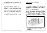
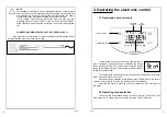
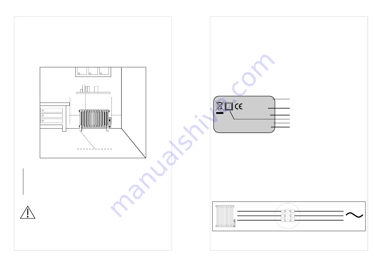
To ensure your system is safe (see figure)

:

- ensure that an area of at least 50 cm in front of the 

appliance is clear of objects which might hinder air 

circulation (furniture, chairs, etc.);

- position a shelf at least 10 cm above the top of your 

radiator;

- use mounting screws suitable for your wall.

IMPORTANT

 This radiator should never be installed with 

the control unit positioned topside.

IMPORTANT

 The system must be fitted with an omni

-

polar circuit-breaker with a minimum contact opening of 

3mm.

ATTENTION

Always turn off the electricity supply (circuit-

b pilot wire) before making any connections. 

≥ 100 mm

≥ 100 mm

100

mm

≥ 500 mm

2.2 Positioning your appliance

To get the most out of your appliance and enjoy the highest standards of 

comfort, we recommend that you install the appliance near places with high heat loss 

(windows, doors, etc.) wherever possible.

You will find a complete set of assembly instructions in your appliance’s box.

2.3 Connecting the appliance

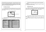
The technical specifications of your radiator are shown on its nameplate.

Please note these down before installing it and before requesting any after-

sales assistance.

When connecting the appliance to the mains, you must observe:


• the voltage indicated on the nameplate;


• conventional colour coding:


– blue or grey: neutral


– brown: live


– black: pilot wire

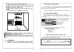
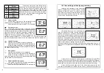
CONNECTING PRINCIPLE WITH PILOT WIRE (CLASS 2):

Your appliance is equipped with a pilot wire for connection to a pilot wire 

programming base unit (not supplied with the appliance).

IP: protection level of your appliance against the 

ingress of solid foreign bodies and water spray 

Voltage and power required for installation

Appliance reference number

Class II: double insulated

OF: serial number

Manufacturer code

ATTENTION NE PAS COUVRIR IP XX

XXXXX

XXXX–XXX–XXX

230V ~ XXXXW

OF: XXXXXXXXXX XXXXXX

N CONSTRUCTEUR XXXXXX

N (blue or grey)

Neutral

Live

Pilot wire (base unit)

L (brown)
Pilot wire (black)

Summary of Contents for Bisque 4FE-40-106/F

Page 1: ... F 24 32 40 46 24 33 38 45 26 34 45 53 67 475 475 475 475 575 575 575 575 675 675 675 675 675 642 826 1010 1148 550 734 826 964 504 642 826 964 1194 136 136 136 136 136 136 136 136 136 136 136 136 136 Weight kg Height 2mm Length 2 Depth 2mm 750 1000 1250 1500 750 1000 1250 1500 750 1000 1250 1500 2000 2559 3412 4265 5118 6824 2559 3412 4265 5118 2559 3412 4265 5118 Output Watts BTU Issue 10 0 Elec...

Page 2: ...ed outside the bathroom Note for maintenance purposes cable outlets must remain accessible and cables must not be buried directly into walls FITTING INSTRUCTIONS Wall plugs 10mm Screws 7mm diameter x 60mm length Wall plugs 10mm Tape measure Spanner 13mm Socketdriver 10mm long reach Electric drill Masonry drill bit 10mm diameter Spirit level Tools Material Required Electric Classic Radiator A E B C...

Page 3: ...lack of experience and knowledge if they have been given supervision or instruc tion concerning use of the appliance in a safe way and understand the hazards involved Children shall not play with the appliance Cleaning and user maintenance shall not be made by children without supervision This appliance should be plugged or connected accor ding to rules and standards in application only by an auth...

Page 4: ...nd the room temperature when the appliance is switched on this principle also ensures consistent and sustained heating even when the element is no longer powered 2 Installing your appliance 2 1 Warnings The flexible cable supplied with your appliance is desi gned to be connected to the mains via a junction box that must be placed behind the appliance with no need for a plug Typically a fused spur ...

Page 5: ... wherever possible You will find a complete set of assembly instructions in your appliance s box 2 3 Connecting the appliance The technical specifications of your radiator are shown on its nameplate Please note these down before installing it and before requesting any after sales assistance When connecting the appliance to the mains you must observe the voltage indicated on the nameplate conventio...

Page 6: ...blue or grey 3 Operating the electronic control 3 1 Description of control unit The ON Stand by button switches the regulator ON or puts it on standby when the device is on standby the display shows a flashing writing St by while when it is ON the display shows time and program in the Chrono mode or the temperature setting in the other modes The buzzer emits one beep after the transition from STAN...

Page 7: ...p to the current setpoint temperature value the one shown in the Comfort mode FROST PROTECTION position Your radiator is set to ensure a minimum temperature of 7 C in your room to prevent any risk of frost All the pilot wire commands except STOP are disabled Chrono Pilot wire Comfort Eco Frost protection 3 3 Time setting and hourly programming Hold down the ON standby and Function buttons simultan...

Page 8: ...d see table Setpoint temperature Pilote Wire signal Display Temperature COMFORT Setpoint temperature REDUCTION Setpoint temperature 3 5 ECO1 Setpoint temperature 1 C ECO2 Setpoint temperature 2 C FROST PROTECTION 7 C STOP Stop The STOP command is enabled in all modes except for the standby state If the STOP command was implemented outside of the mode Pilote Wire the icon blinks With the STOP comma...

Page 9: ...e appliance s nameplate the sales reference for your appliance shown on your dated purchase invoice Guarantee See general conditions of sale for your country The heating body of your electric radiator is guaranteed against manufacturing defects for five 5 years from the date of purchase while the electrical components are guaranteed for two 2 years It complies with the EMC Directive 2004 108 EC re...

Reviews: