
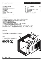
10
11
Z23720
Z23720
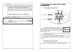
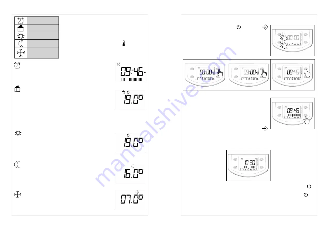
Temperature settings are at two different levels,
setpoint and eco. Setpoint temperature is used by the
Chrono, Pilot wire and Comfort modes. Eco tempera-
ture is used by the Chrono and Eco modes. The set-
point temperature can be modified only in the Comfort
mode and the eco one only in the Eco mode using the
+
and
–
buttons. The thermometer symbol flashes when
modification is taking place.
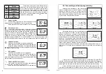
Chrono position:
Shows weekly programme at two temperature levels
(setpoint and eco) established by the user hour by hour.
All the pilot wire commands, except STOP, are disabled
Pilot wire position:
This position makes it possible to select the operating
setting for your radiator remotely, using a programming device.
A pilot wire programming unit sends an instruction via the black
pilot wire to which your radiator is connected. It switches your
radiator to one of its settings (FROST PROTECTION, ECO,
COMFORT, STOP) and can also switch your radiator to two
additional settings (COMFORT -1°C and COMFORT -2°C). See the instructions with
your pilot wire programmer for how to use your radiator with a pilot wire programmer.
CONFORT position:
Unlimited time regulation for setpoint temperature
All the pilot wire commands except STOP are disabled.
During the setting modification, the setpoint temperature
could be decreased until the current eco temperature value (the
one shown in the Eco mode)
ECO position:
Unlimited time regulation for eco temperature
All the pilot wire commands except STOP are disabled.
During the setting modification, the eco temperature
could be increased up to the current setpoint temperature value
(the one shown in the Comfort mode).
FROST PROTECTION position:
Your radiator is set to ensure a minimum temperature of
7°C in your room, to prevent any risk of frost.
All the pilot wire commands except STOP are disabled.
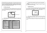
Chrono
Pilot wire
Comfort
Eco
Frost
protection
3.3 Time setting and hourly programming
Hold down the ON/standby and Function
buttons simultaneously for at least 3 seconds. The day
dot begin to flash. Use
+
and
–
to set the current day
and confirm by pressing the function button. Set the
hours and minutes in the same way. The day is marked
by a dot on the vertical numbered scale.
After setting the time, go on to weekly program-
ming. Set a sequence for each hour and each day of
the week. Use the
+
and
–
buttons to make selections.
The
+
button indicates setpoint temperature regulation
for that time and the
–
button indicates eco temperature
regulation. The segments on the time setting bar cor-
respond to setpoint temperature and the empty space
corresponds to eco temperature. Press the Function
button to save the day’s settings, then start the same
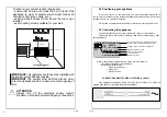
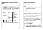
procedure for the next day. For example, to set the setpoint temperature from 6 to 10
and from to 17 to 23 (and the eco temperature in the other time slots), see the following
picture:
If, during the time setting and weekly program, the ON/Stand-by button is
pressed, the device goes into stand-by state, saving the new timing/date while the new
weekly program is not saved. With a new pressing on the ON/Stand-by button , the
device goes into ON state into the mode that was present before the time setting.
In case of 230Vac supply power cut off, the chrono weekly program, the set-
point and eco temperature are retained into the memory, instead the current time is
Day
Hour
Minutes


