20 - EN
Assign the second connected digital input of the
3 Position switch to option 2 “Ventilation speed
2” (in the case of the schematic displayed in the
installation chapter this is digital input 5).
Assign the third connected digital input of the 3
Position switch to option 1 “Ventilation speed 1”
(in the case of the schematic displayed in the
installation chapter this is digital input 6).
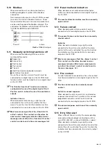
SAG 0-M (M09 option 3)
When a “SAG 0-M” switch is
present, the switch must be
assigned in parameter M09 to the
“Proportional ventilation” function.
Check which analog input the
switch is connected to and choose
option 3 for that analog input/switch.
When the switch is fully opened (10V) the unit will run
on the set air volume of ventilation speed 4. When
the switch is fully closed (0V) the fans of the unit will
turn off.
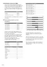
6.6 Sensor (0..10V) control
(M02-10 M04-11,
M09)
When using a sensor to control the ventilation, the
unit must be set to option 3 “0..10V (positive)” or
option 4 “0..10V (negative)” in M02-10. (see chapter
“Air volume control” to learn the difference between
positive and negative control)
Each connected sensor must be assigned in
parameter M09 to the correct “air flow” function.
Check the location of sensor connected and to
which analog input the sensor is connected and
choose option 8 for a supply sensor or option 9 for
an exhaust sensor for that analog input/sensor.
The preset value of the desired setpoint can be
changed in parameter M02-15 (supply air) and/or
M02-16 (exhaust air).
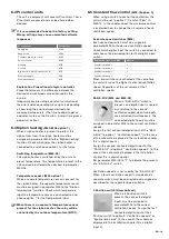
Only one sensor present (M04-11)
When only one sensor is present, an air ratio factor
must also be set in parameter M04-11.
6.7 Constant pressure control
(M02-10,
M04-11, M09)
When using a pressure sensor to control the
ventilation, the unit must be set to option 1
“Constant Pressure (positive)” or option 2 “Constant
Pressure (negative)” in M02-10. (see chapter “Air
volume control” to learn the difference between
positive and negative control)
Each connected pressure sensor must be assigned
in parameter M09 to the correct “air pressure”
function. Check the type of sensor connected and
to which analog input the sensor is connected and
choose the correct option for that analog input/
sensor.
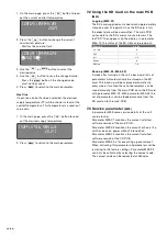
Pressure functions in M09
Option
0..500Pa supply
4
0..500Pa exhaust
5
0..300Pa supply
6
0..300Pa exhaust
7
The preset value of the desired pressure setpoint
can be changed in parameter M02-11 (supply air)
and/or M02-12 (exhaust air).
Only one sensor present (M04-11)
When only one pressure sensor is present, an air
ratio factor must also be set in parameter M04-11.
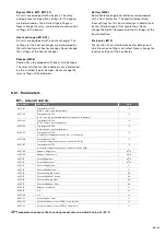
6.8 Switch to second setpoint
(M02, M05
option 25)
When a switch is present to switch to a second
setpoint, the switch must be assigned in parameter
M05 to the “Second setpoint select” function. Check
which digital input the switch is connected to and
choose option 25 for that digital input/switch.
Constant pressure control (M02-13, M02-14)
When the ventilation setting of the unit is controlled
by one or more pressure sensors the preset value
of the desired second setpoint can be changed
in parameter M02-13 (supply air) and/or M02-14
(exhaust air).
Sensor (0..10V) control (M02-17, M02-18)
When the ventilation setting of the unit is controlled
by one or more sensors , the preset value of
the desired second setpoint can be changed in
parameter M02-17 (supply air) and/or M02-18
(exhaust air).
Summary of Contents for ComfoAir 1500
Page 1: ...ComfoAir XL ComfoAir Eco Manual Cooling Fresh Air Clean Air Heating...
Page 45: ...EN 45...
Page 46: ...46 EN...
Page 47: ...EN 47...

