20 - EN
EN - 21
6.9 Summer night ventilation
(M02-09, M05
option 21, M06 option 10)
When a switch is present to switch to summer night
ventilation, the switch must be assigned in parameter
M05 to the “Enable Summer Night Ventilation”
function. Check which digital input the switch is
connected to and choose option 21 for that digital
input/switch.
Ventilation speed (M02-09)
The unit is preset with one of the standard ventilation
speeds. The preset ventilation speed can be
changed in parameter M2-09 to any of the standard
ventilation speeds.
Indicator (M06 option 10)
When an indicator (e.g. a light) is present to verify
whether the summer night ventilation is active, the
indicator must be assigned in parameter M06 to the
“Summer night ventilation active” function. Check
which relay the indicator is connected to and choose
option 10 for that relay/indicator.
When the summer night ventilation is active the
bypass is always open.
6.10 Modbus
(M80)
The unit is fitted with an Modbus connection for
connecting to a building management system.
Modbus will use menu M30 to change the settings
of the digital inputs and the ventilation speed. The
Modbus protocol of the unit can be requested from
Zehnder. In menu M80 the address, baud rate and
parity settings of the Modbus must be programmed
first.
6.11 Manually switching functions off
(M05)
When a switch is present to manually switch off a
function, this switch must be assigned in parameter
M05 to the correct “Enable” function. Check which
function the switch must have and which digital input
the switch is connected to and choose the correct
option for that digital input/switch.
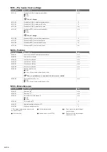
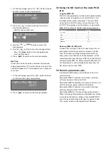
Enable functions in M05
Option
Enable supply fan
14
Enable exhaust fan
15
Enable post-heater
16
Enable post-cooler
17
Enable ComfoAir XL
19
Heat/Cool mode
(coolmode = closed)
22
Enable time clock
26
The balanced ventilation function is overruled
when using the enable fan function.
Indicator fans on (M06 option 8)
When an indicator (e.g. a light) is present to verify
whether the fans are on, the indicator must be
assigned in parameter M06 to the “ComfoAir XL
active” function. Check which relay the indicator is
connected to and choose option 8 for that relay/
indicator.
6.12 Reset malfunction button
(M05 option
23, M06)
When a switch is present to reset the failures of the
unit, the switch must be assigned in parameter M05
to the “Reset all failures” function. Check which
digital input the switch is connected to and choose
option 23 for that digital input/switch.
6.13 Failure contact
(M05 option 18, M06)
When a failure contact is present to detect a general
failure, this contact must be assigned in parameter
M05 to the “Failure” function. Check which digital
input the failure contact is connected to and choose
option 18 for that digital input/contact.
The used failure contact must be a breaker contact.
Indicator (M06 option 1)
When the failure contact of the unit is activated, the
corresponding error message will be displayed on
the display of the main PCB.
When an indicator (e.g. a light) is present to verify
whether the failure contact of the unit is activated,
the indicator must be assigned in parameter M06 to
the “Alarm” function. Check which relay the indicator
is connected to and choose option 1 for that relay/
indicator.
6.14 Fire contact
(M02, M05 option 20/24)
When a fire contact is present to switch to a
fire response/scenario, the fire contact must be
assigned in parameter M05 to the “Fire Contact”
function. Check which digital input the fire contact
is connected to and choose option 20 for that digital
input/fire contact.
Switch to second response (M05 option 24)
When a switch is present to switch to an alternative
fire response/scenario, the switch must be assigned
in parameter M05 to the “Enable Fire overrule”
function. Check which digital input the switch is
connected to and choose option 24 for that digital
input/switch.
Fire response scenarios (M02 option 19-22)
The unit can be programmed with two fire esponse/
scenarios. The wanted standard response can
be programmed in parameter M02-19 (supply air)
and M02-20 (exhaust air). The wanted alternative
response can be programmed in M02-21 (supply air)
and M02-22 (exhaust air).
Summary of Contents for ComfoAir 1500
Page 1: ...ComfoAir XL ComfoAir Eco Manual Cooling Fresh Air Clean Air Heating...
Page 45: ...EN 45...
Page 46: ...46 EN...
Page 47: ...EN 47...


