7 - EN
2.4 Installation conditions
In order to determine whether the ComfoAir can be
installed in a certain area, the following aspects must
be taken into account:
■
The ComfoAir must be installed according to the
general and locally applicable safety and installa-
tion regulations of power and water companies, as
well as the instructions in this manual.
■
The system must be fitted to allow sufficient room
around the ComfoAir for the air connections and
supply and exhaust ducts as well as for carrying
out maintenance activities.
■
The ComfoAir must be installed in a frost-free space.
The condensation must be drained off frost-free, at a
gradient and incorporate a 'U' bend.
We do not recommend installing the Com-
foAir in areas with a higher average humidity
(such as bathroom or toilet). This will prevent
condensation on the outside of the ComfoAir.
■
The room must offer the following provisions:
- Air duct connections.
- 230V electrical connection.
- Provisions for the condensation drain.
- Wiring for a wired 3-position switch
(optional).
■
A gap should be left near the doors in order to
ensure effective and draughtfree airflow in the
house. A gap under the inside doors must be at
least 10mm.
If these openings are obstructed, due to
draught excluders or deep-pile carpet, the
airflow in the house will stagnate. As a result,
system performance will be compromised or
fail altogether.
2.5 Installation of the ComfoAir
2.5.1 Transport and unpacking
Take the necessary precautions when transporting
and unpacking the ComfoAir.
Make sure the packing material is disposed
of in an environmentally friendly manner.
2.5.2 Checking the delivery
Contact your supplier immediately in case of dam-
age or an incomplete delivery. The delivery should
include:
■
ComfoAir;
Check the identification plate to ensure that it is
the required type.
■
Ceiling mounting set;
■
Wall mounting bracket;
■
Documentation.
The ComfoAir is supplied in the following types:
Type
ComfoAir 200 L Basic
ComfoAir 200 R Basic
ComfoAir 200 L Luxe
ComfoAir 200 R Luxe
ComfoAir 200 L Luxe PH
ComfoAir 200 R Luxe PH
Meaning of the suffixes:
■
L
=
Left version
■
R
=
Right version
■
PH =
Contains a pre heater by default.
■
Luxe =
Contains a connection board
with extra function by default.
ComfoSense panel (optional) can be ordered sepa-
rately.
2.6 Mounting of the ComfoAir
The ComfoAir can be mounted two ways:
■
On the ceiling;
■
On the wall.
2.6.1 Mounting on the ceiling
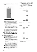
Mount the ComfoAir to a ceiling with a minimum
mass of at least 200 kg/m
2
.
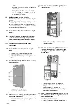
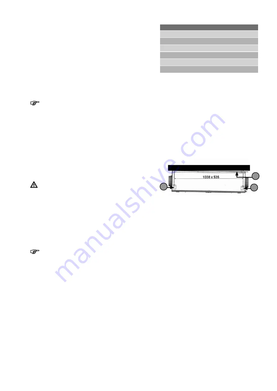
B
A
C
1. Fasten the four mounting brackets (A) (using the
screws supplied) to the sides of the ComfoAir.
2. Fasten the two spacer brackets (C) (using the
screws supplied) to the top of the ComfoAir on
the side of the condensation drain (B). As long as
the ceiling is level, this ensures a run-off of 2% to
the condensation drain.
3. Mark the position of the mounting points on the
ceiling.
4. Mount four pieces of studding (M8 or M10) exten-
ding 290 cm below the ceiling.
5. Screw suitable (securing) rings and nuts on the
four rods.
6. Hang the unit on the rods and then screw the
locknuts tight.
Allow a minimum 2% run-off to the condensation
drain. If the ceiling is horizontal, the spacer brak-
kets will automatically ensure that the ComfoAir
hangs at the correct angle.
7. Mount the condensation drain to the ComfoAir
with a coupling or removable pipe.
8. The air exhaust duct must be fitted with a double-
walled or insulated roof passage. This prevents
the formation of condensation between the roof
boarding. In addition, the air exhaust duct must
drain in the direction of the ComfoAir.
9. To prevent unnecessary temperature loss in eit-
her the summer or the winter, we recommend
fitting thermal and damp-proof insulation to the
supply ducts from the ComfoAir up to the supply
valves.
Ensure that there is enough room under the ComfoAir
for carrying out maintenance. The ComfoAir does not
require any space at the sides for effective operation.

