9 - EN
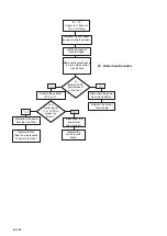
2.6.4 Connection of the condensation drain
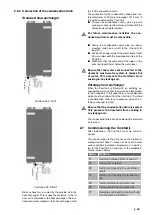
Standard heat exchanger
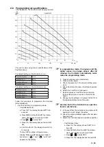
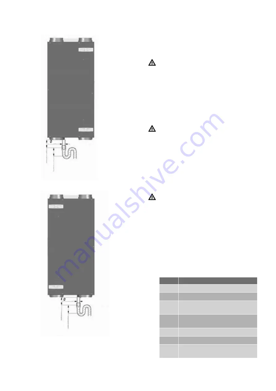
min 60 mm
min 60 mm
20 mm
ComfoAir 200 - LEFT
min 60 mm
min 60 mm
20 mm
ComfoAir 200 - RIGHT
Warm exhaust air is cooled by the outside air in the
heat exchanger. This causes the moisture in the in-
door air to condense in the heat exchanger. The con-
densation water created in the heat exchanger is fed
to a PVC condensation drain.
The connection for the condensation drain has an ex-
ternal diameter of 20 mm and a ledge of 21.2 mm. It
is located underneath the ComfoAir.
■
Connect the condensation drain, via a pipe with
coupling or hose, to the water seal (U bend) of the
domestic waste-water system.
For future maintenance activities the con-
densation drain must be removable.
■
Ensure the condensation drain pipe on ceiling-
mounted units has a run-off to the U bend of at
least 2%.
■
Position the upper edge of the water seal at least
40 mm underneath the condensation drain of the
ComfoAir.
■
Make sure that the outer end of the pipe or tube
exits is at least 60mm below the water level.
Ensure that the water seal connected to the
domestic waste-water system is always full
of water. This prevents the ComfoAir from
sucking in any leakage air.
Enthalpy heat exchanger
When the ComfoAir is fitted with an enthalpy ex-
changer the moisture from the indoor air is transferred
to the outside air. In this case there is no condensate
which must be drained from the ComfoAir. Therefore
a condensation drain is not necessary when an en-
thalpy exchanger is fitted.
Ensure that the condensation drain is sealed.
This prevents the ComfoAir from sucking in
any leakage air.
The condensation drain can be sealed with a standard
screw-cap.
2.7 Commissioning the ComfoAir
After installation, the ComfoAir must be commis-
sioned.
This can be done via the P menus on the digital op-
erating device. These P menus can be used to enter
various settings (ventilation programmes, in particu-
lar) for the ComfoAir. An overview of the available P
menus is given below:
Menu
options
P1
Reading statuses (from menu P2)
P2
Setting time delays
P3
Setting and reading the ventilation
levels
P4
Setting and reading the temperatu-
res
P5
Setting additional programmes
P6
Setting additional programmes
P7
Reading and resetting malfunctions
(and system information)

