background image

 17 - EN

hot water (max. 40 °C).

b.   Rinse the heat exchanger with clean hot tap wa-

ter (max. 40 °C).

c.   Clasp the heat exchanger between both hands 

(on the coloured side surfaces) and shake the 
water from the heat exchanger.

 Only an enthalpy exchanger with a blue co-
ver can be washed with water. When having 
an enthalpy exchanger with a white cover 
never wash it with water.

 Do not use aggressive cleaning agents or 
solvents.

 If the fans or preheater element filter also 
need maintenance do not re-install the heat 
exchanger yet.

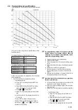
10. 

If no more maintenance is necessary install 

all parts in reverse order, reconnect the pow-

er and carry out the self-test in accordance 

with menu P76

.

 Fasten the screws to a maximum of 1.5 Nm. 
This is roughly equal to setting 2 of an ave-
rage battery-powered drill.

2.9.2  Inspecting and cleaning the fans

 Check the fans once every 2 years.

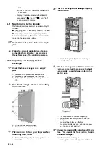
1.   Remove the heat exchanger as instructed in the 

maintenance chapter of the heat exchanger 

2. 

Remove

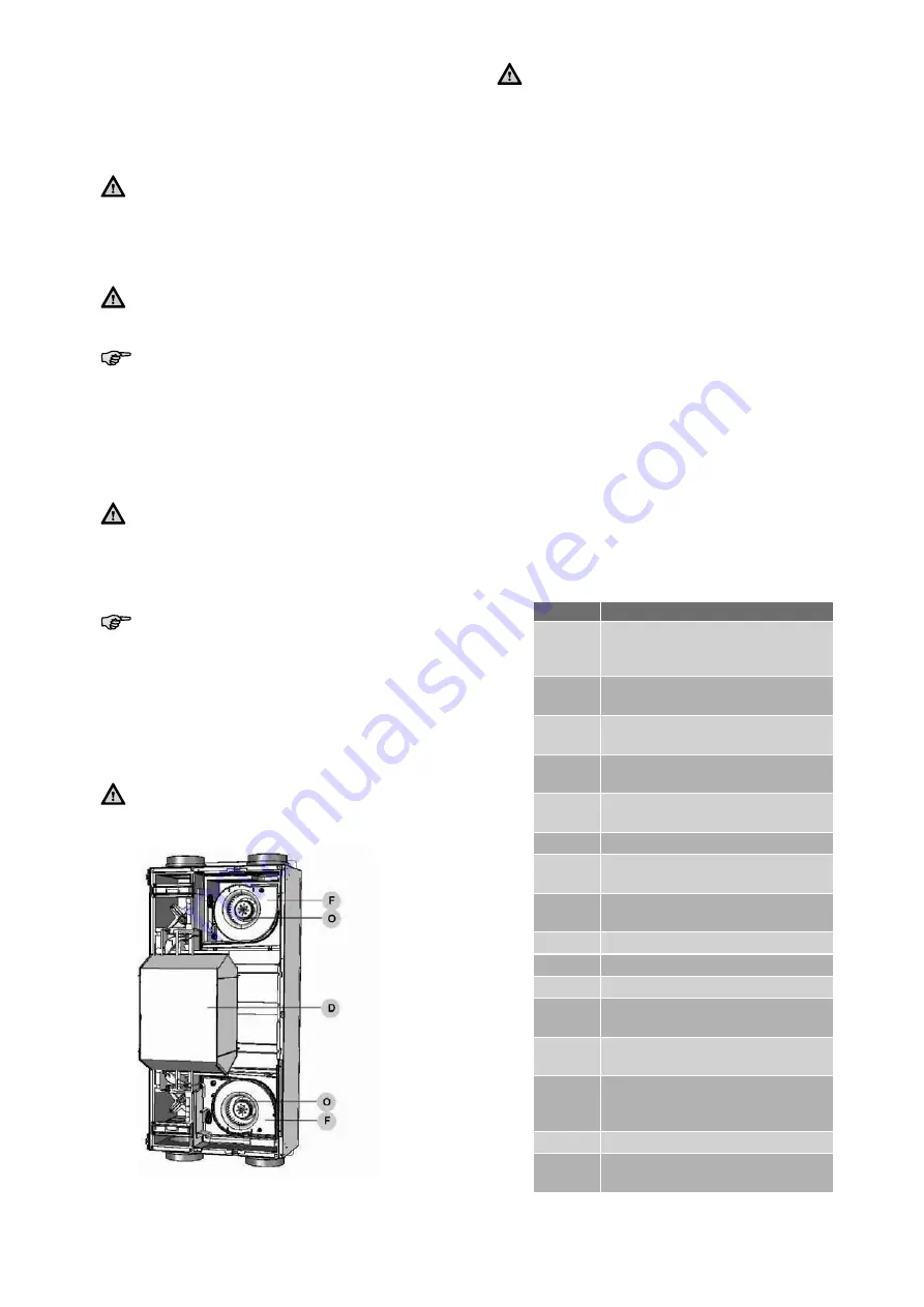
 the inflow nozzle (F) by unscrewing the 

2 screws  surrounding the scroll casing.

3.  Inspecting and if necessary clean the fans (O).
 

- Use a soft brush to clean the fan impellers.


- Use a vacuum cleaner to remove dust.

 Do not damage the fan impellers or tempe-
rature sensor.

4. 

Install

 all parts in reverse order.

5. 

Carry out

 the self-test in accordance with menu 

P76.

 Fasten the screws to a maximum of 1.5 Nm. 
This is roughly equal to setting 2 of an ave-
rage battery-powered drill.

2.10 Malfunctions

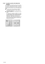
Malfunctions in the ComfoAir are reported as follows:

  The malfunction alert appears on the ComfoS-

ense panel;

  The malfunction alert appears on the display;

  The malfunction indicator on the 3-position 

switch lights up.

Malfunction alerts may not appear on the digital oper-
ating device in all cases, even though there is a mal-
function (or problem). A concise explanation of both 
types of malfunction (or problem) is given in the fol-
lowing paragraphs.

2.10.1 Malfunction alerts on the digital 

operating device

In the event of a malfunction, the corresponding mal-
function code will be displayed on the digital operat-
ing device of the ComfoAir.

Below is a list of the malfunction alerts on the digital 
operating device.
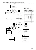
In the chapter about troubleshooting is explained 
how to solve these malfunctions

Code

Description

A0

NTC sensor TGe is defective.
(=  geothermal heat exchanger tem-
perature)

A1

NTC sensor T1 is defective.
(= outside air temperature)

A2

NTC sensor T2 is defective.
(= supply air temperature)

A3

NTC sensor T3 is defective.
( =return air temperature)

A4

NTC sensor T4 is defective.
(= exhaust air temperature)

A5

Malfunction in the bypass motor.

A6

Malfunction in the 
Pre heater motor.

A7

Pre heater does not heat suffi-
ciently.

A8

Pre heater becomes too hot

E1

Exhaust fan not rotating.

E2

Supply fan not rotating.

EA1

Enthalpy sensor measures exces-
sive Relative Humidity (RH) values.

EA2

No communication between the 
enthalpy sensor and the ComfoAir.

COMM 
ERROR

No communication between the 
ComfoSense panel and the Com-
foAir.

FLTR

Internal Filter is dirty.

FLTR 
EXT 

External Filter is dirty.

Summary of Contents for ComfoAir 200

Page 1: ...Cooling Fresh Air Clean Air Heating ComfoAir 200 Installer manual...

Page 2: ...has been compiled with the utmost care The publisher cannot be held liable for any damage caused as a result of missing or incorrect information in this manual In case of dis putes the Dutch version...

Page 3: ...rain 9 2 7 Commissioning the ComfoAir 9 2 7 1 Display on the unit 10 2 7 2 P menus for the installer 11 2 8 Programming air specifications 15 2 9 Maintenance by the installer 16 2 9 1 Inspecting and c...

Page 4: ...EN IV...

Page 5: ...ly be submitted for ma terial faults and or construction faults arising during the warranty period In the case of a warranty claim the ComfoAir must not be dismantled without written permission from t...

Page 6: ...e ComfoAir throughout its life Instructions with regard to cleaning or replacing the filters of the intake and exhaust valves must be carefully observed The specifications stated in this document may...

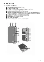
Page 7: ...or programming procedures optional Control circuit board H with connections for the fans the bypass the Pre heater temperature sensors T1 to T4 the 3 position switch with or without malfunction indica...

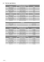
Page 8: ...ng 185 m3 h at 68 Pa 0 55 A Maximum 255 m3 h at 125 Pa 1 10 A Electricity Power supply 230 50 V Hz Cos phi 0 48 0 57 Supply fan noise level at 0 m Position Ventilation capacity Sound power Absent Sett...

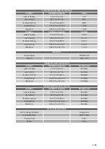
Page 9: ...ty Power supply 230 50 V Hz Cos phi 0 48 0 57 Supply fan noise level at 0 m Position Ventilation capacity Sound power Absent Setting 20 m3 h at 3 Pa 37 dB A Low Setting 90 m3 h at 13 Pa 53 dB A Medium...

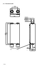
Page 10: ...EN 6 2 3 Dimension sketch LEFT RIGHT CONDENSATION DRAIN...

Page 11: ...ting bracket Documentation The ComfoAir is supplied in the following types Type ComfoAir 200 L Basic ComfoAir 200 R Basic ComfoAir 200 L Luxe ComfoAir 200 R Luxe ComfoAir 200 L Luxe PH ComfoAir 200 R...

Page 12: ...air ducts Install the air exhaust duct so it drains in the di rection of the ComfoAir Insulate the outside air supply and the air ex haust duct between the roof wall passage to render the ComfoAir da...

Page 13: ...level Ensure that the water seal connected to the domestic waste water system is always full of water This prevents the ComfoAir from sucking in any leakage air Enthalpy heat exchanger When the Comfo...

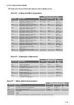
Page 14: ...es Bypass Access to the menus Se quence Press Display Description 1 MENU P2 Time delay 2 s 3 seconds P3 Press the buttons simultaneously 3 s P4 Temperatures 4 s P5 Settings 5 s P6 Settings 6 s P7 Malf...

Page 15: ...capacity in of the supply fan in medium position 17 99 nL HL 50 70 P37 Setting the capacity in of the supply fan in high position 18 100 nL HL 70 90 P38 Current capacity in of the exhaust fan Current...

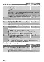
Page 16: ...me nL HL HL Setting the air volume is the starting point for programming the air specifications and setting the fans P57 Setting the ComfoAir type Li Left hand version Re Right hand version Li Re Li W...

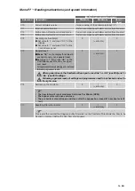
Page 17: ...t least 5 seconds to carry out a general reset Set value to 1 and press OK on the ComfoSense panel to carry out a gen eral reset All original software settings are restored following a general reset 0...

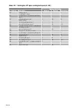
Page 18: ...3 min setting analogue input 1 0 99 0 814 max setting analogue input 1 0 100 100 815 0 positive analogue input 1 1 negative set ting analogue input 1 0 1 0 816 read out analogue input 1 0 100 850 RF i...

Page 19: ...ppears on the display In programming mode the bypass and Pre heater valves are always closed After 30 minutes the ComfoAir automatically termi nates the programming mode 2 Close all windows and outsid...

Page 20: ...lter caps from the ComfoAir 3 Release the front panel by unscrewing the screws C The front swings forward on ceiling mounted units 4 Lift front panel from its hinges 5 Disconnect condensation drain Ta...

Page 21: ...powered drill 2 10 Malfunctions Malfunctions in the ComfoAir are reported as follows The malfunction alert appears on the ComfoS ense panel The malfunction alert appears on the display The malfunctio...

Page 22: ...tion switch with malfunction indicator In the event of a malfunction or filter dirty alert the indicator lights up Wireless 3 position switch with malfunction indi cator The malfunction indicators wil...

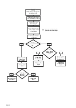
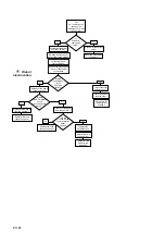
Page 23: ...esistance of the NTC sensor correct Replace the NTC sensor Replace the control circuit board Set P51 on 0 and P57 to the correct value see rating plate A7 Malfunction Reset the malfunction P74 on 1 Se...

Page 24: ...t panel from its hinges Did the bypass pre heater motor run Yes Disconnect the power from the ComfoAir Replace the control circuit board Remove the motor Disconnect the power from the ComfoAir Is the...

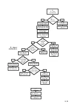
Page 25: ...place Pre heater cable Yes No Are the connections at the pre heater correct Replace Pre heater Reconnect the pre heater Install all parts in reverse order Reconnect the power to the ComfoAir Is P51 an...

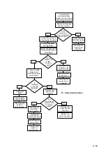
Page 26: ...the self test P76 on 1 Check the following Fan settings to low Supply valve s to far closed Supply air ducts blockages Version settings P57 correct value No Yes Did the pre heater valve open and clos...

Page 27: ...correct A10 Malfunction Set P53 on 0 Reset the malfunction P74 on 1 Replace the NTC sensor Install all parts in reverse order Reconnect the power to the ComfoAir Install all parts in reverse order Re...

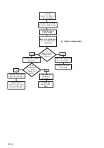
Page 28: ...an Yes No Disconnect the power from the ComfoAir Replace the control circuit board Is a control signal 1 5 10 VDC present on the fan Yes No Disconnect the power from the ComfoAir Replace the control c...

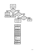
Page 29: ...fit the leakage tray of the ComfoAir See the maintenance chapter of the heat exchanger Was there a lot of moisture in the environment Fil tEr Internal Filter is dirty Press OK on the display for at le...

Page 30: ...re 12VDC present on the Luxe connection panel Yes Disconnect the power from the ComfoAir Replace the Luxe connection panel Are the fuses on the Luxe connection panel correct Yes No Disconnect the powe...

Page 31: ...Reconnect the power to the ComfoAir Disconnect the power from the ComfoAir COMM ERROR No communication between the ComfoSense panel and the ComfoAir Install all parts in reverse order Reconnect the p...

Page 32: ...n the ComfoSense panel 2x to reset the FLTR warning Disconnect the power from the ComfoAir Remove the filter caps from the ComfoAir Remove the dirty filters from the ComfoAir Slide the clean new filte...

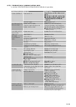
Page 33: ...blocked Clean the ventilation ducts ComfoAir is in frost protection operation Wait until the weather warms up Too noisy Fan bearings defective Replace the fan bearings Fan settings to high Change the...

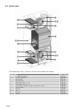
Page 34: ...d Green 400200018 2 Fan Left hand Red 400200019 3 Control panel 400300051 4 Connector panel 400300031 5 Temperature sensor T1 T3 400300049 6 Temperature sensor T2 T4 400300048 7 Servo motor cable for...

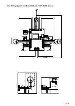
Page 35: ...ellow Brown Blue Blue Brown Red Black White Brown White Brown White Yellow 0 10V Blue L1 Grey L2 Black L3 Brown N Blue CASING SUPPLY EXHAUST RJ45 VENT VENT FIL T2 T4 T1 T3 BYP PIE TRI VENT BS VENT 1 T...

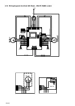
Page 36: ...ellow Brown Blue Blue Brown Red Black White Brown White Brown White Yellow 0 10V Blue L1 Grey L2 Black L3 Brown N Blue CASING SUPPLY EXHAUST RJ45 VENT VENT FIL T2 T4 T1 T3 BYP PIE TRI VENT BS VENT 1 T...

Page 37: ...0 10V M M RS232 Black Red White Brown M White Brown Blue Yellow 0 10V White M DISPLAY Bathroom switch volt free contact Pre heater T3 T2 T1 T4 Pre heater valve Green Yellow Brown Blue Blue Brown Red B...

Page 38: ...0 10V M M RS232 Black Red White Brown M White Brown Blue Yellow 0 10V White M DISPLAY Bathroom switch volt free contact T3 T2 T1 T4 Preheater valve Green Yellow Brown Blue Blue Brown Red Black White...

Page 39: ...4 Company register Zwolle 05022293 EEC declaration of conformity Machine description Heat recovery units ComfoAir 200 series Complies with the following directives Machinery Directive 2006 42 EEC Low...

Page 40: ...EN Subject to change Zehnder Comfosystems A division of Zehnder Group UK Ltd Unit 1 Brookside Avenue Rustington West Sussex BN16 3LF T 44 1903 777 333 F 44 1903 782 398 comfosystems zehnder co uk www...

Reviews: