2.9 Wiring The Unit
Step 1
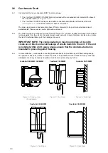
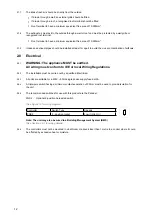
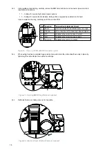
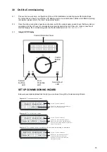
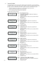
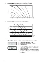
Undo four screws from electrical connection cover and remove
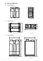
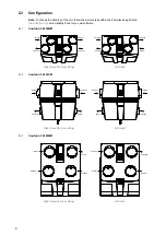
ComfoAir CA155WM
ComfoAir CA185WM
ComfoAir CA155CM
HR155WM
HR185WM
HR155CM
Figure 14 - Top View
Figure 15 - Top View
Figure 16 - Top View
Step 2
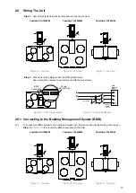
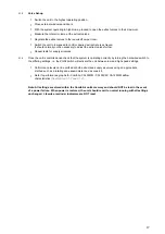
Wire as per wiring diagram into the PCB terminal block.
Upon completion, replace cover and secure with the four screws.
PCB CLOSEUP
BMS
Connection
Wiring
Terminal block
Wiring
E
N
N
L
L
L1
PCB
Terminal
Block
Triple-pole
Isolating
Switch
E
Light Switch
Light
Figure 17 - PCB Terminal Block
Figure 18 - Wiring Specification
2.9.1 Connecting to the Building Management System (BMS)
2.9.2
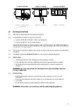
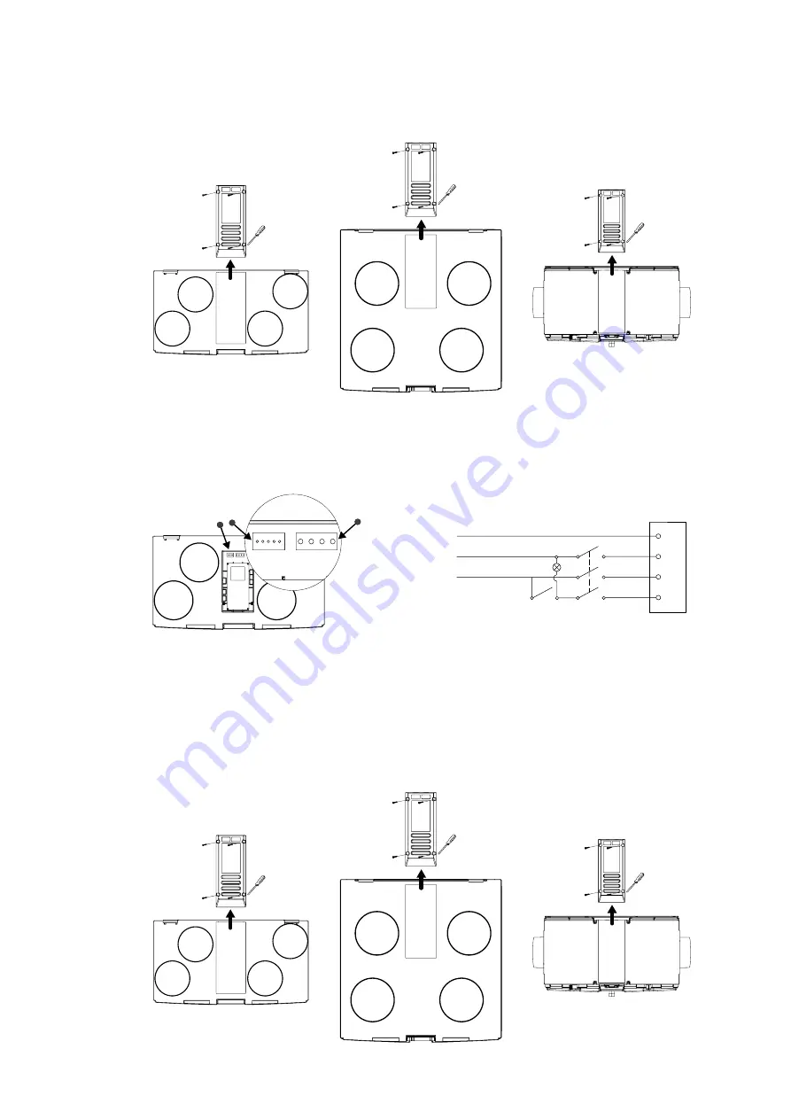
To connect your BMS system to the ComfoAir Compact unit, first remove the electrical wiring cover as per
Step 1
in
Section 2.9
, then locate the BMS connections on the PCB.
ComfoAir CA155WM
ComfoAir CA185WM
ComfoAir CA155CM
HR155WM
HR185WM
HR155CM
Figure 19 - Top View
Figure 20 - Top View
Figure 21 - Top View
13


