
16
3.1.4
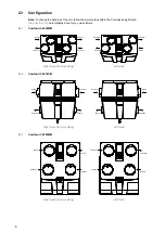
Commissioning Wizard
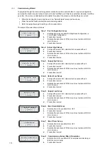
To progress through the commissioning wizard, rotate the controls central button to required configuration
and press the button to select (at each section the text will flash until it has been selected, whereby it will then
go solid). You can move backwards and forwards throughout the process until all settings are correct.
•
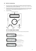
When first turning the power onto the unit, the "Setup Wizard" prompt will be shown.
•
Press the central button to start the commissioning wizard.
•
Refer to design drawings for setting up the required rates.
The steps of the wizard are as follows:
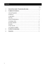
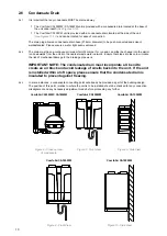
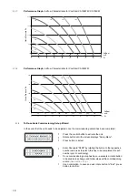
P O R T
C O N F I G :
< R H >
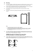
Step 1 Port Configuration Set-up
a
Rotate button to choose either RH (Right Hand Configuration) or
LH (Left Hand Configuration)
b
Press button to select
c
Rotate button and choose FWD to move to next section or BACK to
return to set-up
d
Press button to select
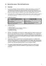
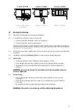
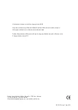
E X T R A C T
H I G H
< 6 6 % >
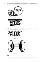
Step 2 Extract High Set-up
a
Factory airflow set at 66%, rotate button to required airflow %
b
Press button to select
c
Rotate button and choose FWD to move to next section or BACK to
return to set-up
d
Press button to select
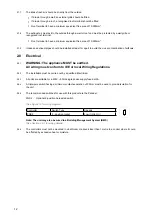
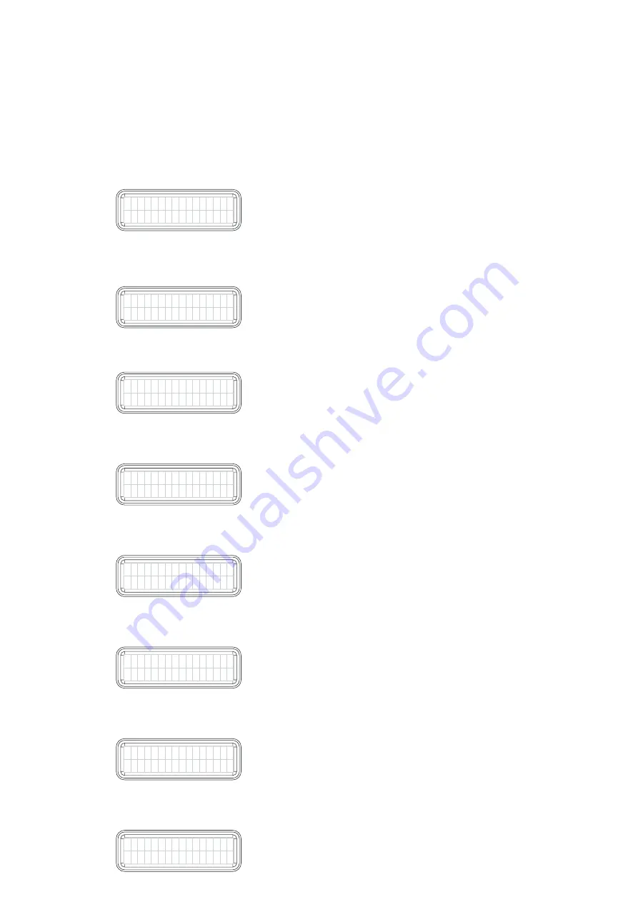
S U P P L Y
H I G H
< 6 6 % >
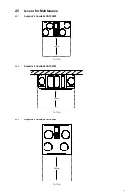
Step 3 Supply High Set-up
a
Factory airflow set at 66%, rotate button to required airflow %
b
Press button to select
c
Rotate button and choose FWD to move to next section or BACK to
return to set-up
d
Press button to select
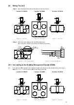
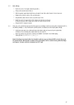
E X T R A C T
L O W
< 3 3 % >
Step 4 Extract Low Set-up
a
Factory airflow set at 33%, rotate button to required airflow %
b
Press button to select
c
Rotate button and choose FWD to move to next section or BACK to
return to set-up
d
Press button to select
S U P P L Y
L O W
< 3 3 % >
Step 5 Supply Low Set-up
a
Factory airflow set at 33%, rotate button to required airflow %
b
Press button to select
c
Rotate button and choose FWD to move to next section or BACK to
return to set-up
d
Press button to select
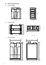
H U M I D I S M A R T
< O N
>
Step 6 Smart Humidity Set-up
a
Rotate button to choose either ON or OFF
b
Press button to select
c
Rotate button and choose FWD to move to next section or BACK to
return to set-up
d
Press button to select
T I M E R S M A R T
< O N
>
Step 7 Smart Timer Set-up
a
Rotate button to choose either ON or OFF
b
Press button to select
c
Rotate button and choose FWD to move to next section or BACK to
return to set-up
d
Press button to select
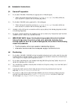
S E T U P
C O M P L E T E
< b a c k
e x i t >
Step 8 Commissioning Set-up Wizard Completion
a
Rotate button to choose either EXIT to complete commissioning or
BACK to return to set-up
b
Press button to select


