background image

2 - EN

Foreword

 Read the manual of the ComfoAir XL and this 

document carefully before use.

This document provides all the additional information 
required for the safe and optimal installation of the 
ComfoAir XL and ComfoAir Eco in three parts. In this 
following document they will be referred to as “the 
unit”. The unit is subject to continuous development 
and improvement. As a result, the unit may slightly 
differ from the descriptions. After reading this 
document you can assemble the three different 
parts (Ventilation, Heat Recovery and Filter section) 
correctly to one complete ComfoAir XL air handling 
unit.

 Questions

Please contact the supplier if you have any questions 
or would like to order a new document or new filters. 
The contact details of the main supplier can be 
found at  the end of this document.

The following pictograms are used in this 
document:

 Point of attention.

 Risk of:


-  damage to the unit;


-  performance of the unit is compromised if 

instructions are not observed carefully.

 Risk of personal injury for the user.

The following terms are used in this document:

  The ‚service side‘ of the unit is referred in the 

document as the ‚front side‘;

  Part 1: Ventilation section (= FAN);

  Part 2: Heat Recovery section (= PHE);

  Part 3: Filter section (= FIL).

All rights reserved.

This document has been compiled with the utmost care. The publisher cannot be held liable for any damage 
caused as a result of missing or incorrect information in this document. In case of disputes the English version of 
this document will be binding.

Summary of Contents for ComfoAir Eco

Page 1: ...Cooling Fresh Air Clean Air Heating ComfoAir XL in three parts Manual for the installer...

Page 2: ...ve any questions or would like to order a new document or new filters The contact details of the main supplier can be found at the end of this document The following pictograms are used in this docume...

Page 3: ...N 3 Table of Contents Foreword 2 1 Safety instructions 4 2 Transport and unpacking 4 3 Installation conditions 4 4 Technical specifications 4 5 Installation 5 6 Testing of the unit 8 7 Commissioning 8...

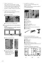
Page 4: ...packed in a plastic bag labelled and placed in a box This box is always situated in the FAN section 3 Installation conditions Follow the installation conditions given in the ComfoAir XL manual Make s...

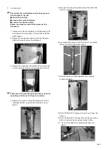
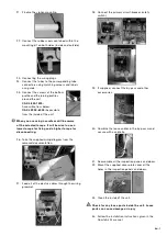
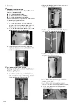
Page 5: ...nside such as the drawing manual wiring diagram DOP etc Take note of the drawing and read the manual for mounting a CA XL unit in 3 parts carefully 4 Remove the screws fixing the three parts to the tr...

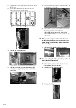
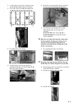
Page 6: ...screws of the bottom profile and the joining profiles around the unit CA XL 800 1500 Accessible from below CA XL 2200 6000 Accessible from the inside of the unit When you are using a cordless drill b...

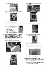
Page 7: ...ll be wise to use a lower torque for fixing and a higher torque for disconnecting 26 Take the supplied wiring diagram from the removed documentation 27 Feed all of the electric cables through the wiri...

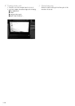
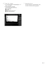
Page 8: ...k wire on digital input 4 5 6 or 7 2 Use the available simulation program for checking the analog input output communication ports digital input and relays 7 Commissioning Follow the commissioning ins...

Page 9: ...ieferanten falls Sie noch Fragen haben oder ein neues Dokument oder neue Filter bestellen wollen Die Kontaktdaten des Hauptlieferanten finden Sie am Ende dieses Dokuments In diesem Dokument werden fol...

Page 10: ...10 DE Inhalt Vorwort 9 1 Sicherheitsanweisungen 11 2 Transport und Entpacken 11 3 Montagebedingungen 11 4 Technische Spezifikationen 11 5 Einbau 12 6 Testen der Anlage 15 7 Inbetriebnahme 15...

Page 11: ...en Kunststoffbeutel in einem Karton verpackt Dieser Karton befindet sich immer in der FAN Sektion 3 Montagebedingungen Die Montagebedingungen in der ComfoAir XL Betriebsanleitung heranziehen Sicherste...

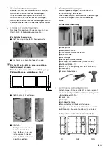
Page 12: ...wie Zeichnung Betriebsanleitung Schaltplan DOP usw herausnehmen Die Zeichnung beachten und die Montageanleitung f r ein CA XL Ger t in drei Teilen sorgf ltig lesen 4 Die Schrauben entfernen mit denen...

Page 13: ...s Bodenprofils und die Verbindungsprofile rund um das Ger t verbinden CA XL 800 1500 Von unten zug nglich CA XL 2200 6000 Von der Innenseite des Ger ts zug nglich Wenn Sie eine Akku Bohrmaschine verwe...

Page 14: ...um Anziehen und einen h heren Drehmoment zum L sen zu verwenden 26 Den mitgelieferten Schaltplan aus der entnommenen Dokumentation heranziehen 27 Alle Elektrokabel durch die Kabeldurchf hrung f hren 2...

Page 15: ...ang 4 5 6 oder 7 anschlie en 2 Zur Kontrolle das verf gbare Simulationsprogramm verwenden Analogeingang Ausgang Kommunikationsanschl sse Digitaleingang und Relais 7 Inbetriebnahme Nach der Anleitung z...

Page 16: ...ehnder Group Nederland B V Lingenstraat 2 8028 PM Postbus 621 8000 AP Zwolle T 31 38 429 69 11 F 31 38 422 56 94 ventilatie zehnder nl www zehnder nl ZGNL_Manual_849050025 0416 EN_DE Subject to change...

Reviews: