6 - EN
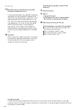
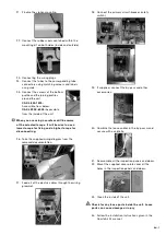
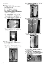
11. Tighten the screws around the unit with an Allen
key (6 mm).
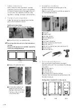
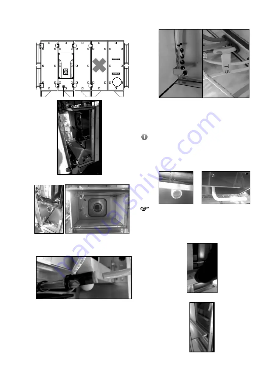
12. CA XL 800-1500: Remove the panel next to
inspection panel of the Ventilator
T5
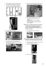
13. Connecting the wiring plugs.
14. Connect the tubes to the corresponding tube
connectors using matching colours and labels
as a guide.
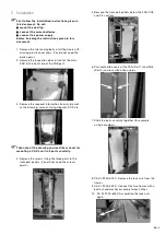
15. Assemble Sensor T5 at the correct position. T5
is labelled with a sticker.
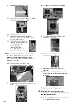
16. Connect the screws of the bottom profile and
the joining profiles around the unit.
CA XL 800-1500:
Accessible from below.
CA XL 2200-6000:
Accessible from the inside
of the unit.
When you are using a cordless drill be aware
of the selected torque. It will be wise to use a
lower torque for fixing and a higher torque for
disconnecting.
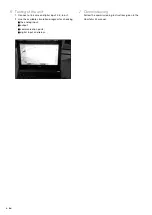
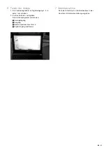
17. Pre mount the supplied drain and siphon.
After assembling the FIL section it‘s possible to
finish the siphon mounting.
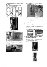
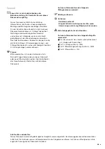
18. Slide the FIL (part 3) section to the already
assembled FAN-PHE sections.
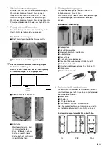
19. Remove the filter inspection door.
20. Remove the filters.


