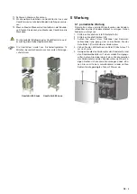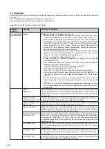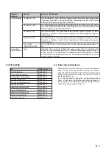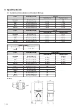
2 - EN
3 Summary and principle
Read this chapter if your are interested in how the Comfo-
Cool works.
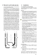
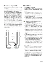
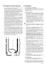
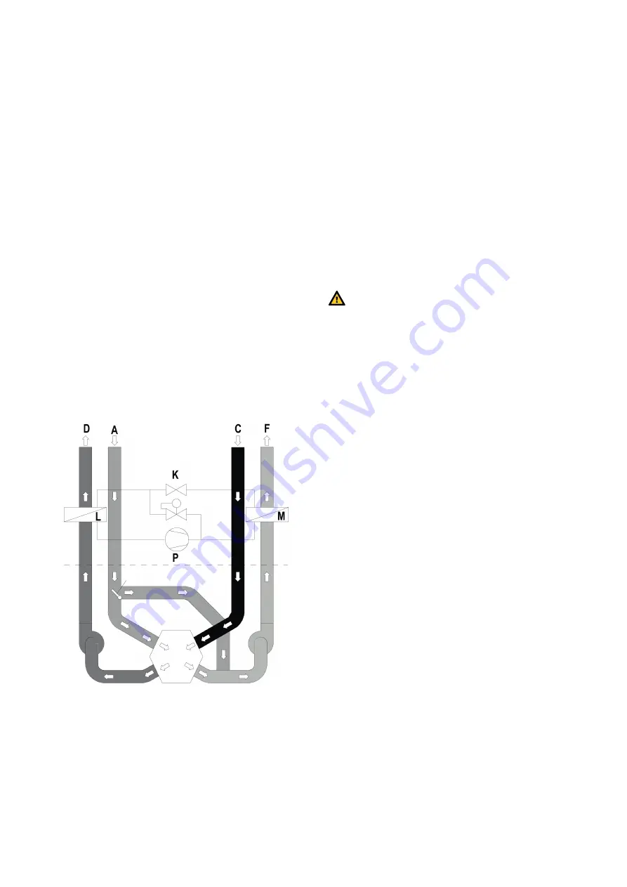
The ComfoCool is equipped with a compression cooling
system, as is used in fridges. The electrically driven com-
pressor
(P)
pumps coolant round the condenser
(M)
, the
capillary
(K)
and the evaporator
(L)
in that order.
In the condenser
(M)
the coolant is converted from a gas to
a liquid (condensation). This process releases energy that is
discharged in the air extracted from the dwelling.
The capillary
(K)
ensures reduced pressure in the cool-
ant, making it boil. This is the opposite effect of a pressure
cooker, which raises boiling point by increasing pressure.
In the evaporator
(L)
the coolant converts from liquid to
vapour. This phased process requires energy, which is
extracted from the supply air
(D)
. This cools the supply air.
The fins of the evaporator
(L)
are colder than the air that
passes them. This creates condensate, dehumidifying the
air. The condensate is drained to the waste-water system.
The result is that energy is transferred from the supply air
(D)
(which becomes cooler and drier as a result) to the
exhaust air
(F)
(which heats up as a result). The combina-
tion of ComfoCool and heat-recovery unit cools more effi-
ciently, as the heat-recovery unit then behaves more like a
“cold-recovery unit” in warm weather. Warm fresh air is pre-
cooled by the heat-recovery unit and is then cooled further
by the ComfoCool.
4 Installation
4.1. Installation conditions
In order to determine whether the ComfoCool can be
installed in a certain area, the following aspects must be
taken into account:
General
• The ComfoCool must be installed according to the gen-
eral and locally applicable safety and installation regu-
lations of power and water companies, as well as the
instructions in this manual.
• The ComfoCool must be installed in a frost-free space
with climate zone N (16-32°C).
• The heat-recovery unit should be mounted on a support
frame (see under service parts), which should stand on
a stable floor. The ComfoCool is placed on an adaptor
set which is then mounted on the heat-recovery unit.
Fitting to a heat-recovery unit mounted on a wall is
NOT permitted for safety reasons.
• The ComfoCool is fitted with fall protection, which
should be firmly attached to the wall.
• The following must be available: Ø180mm air duct con-
nections, 230V electrical connection with sufficient
capacity, and facilities for condensation drainage.
• The roof vents should be made airtight and damp-
proof.
•
ATTENTION: All supply and exhaust ducts should be
damp-proofed.
This prevents condensation forming on
the inner or outer duct surface and improves cooling
efficiency.
• The exhaust duct should drain in the direction of the
unit.
• The condensation must be drained off frost-free, at a
gradient and incorporate a ‘U’ bend.
• DO NOT connect a powered extractor hood to this sys-
tem.
• We recommend fitting the ComfoCool with silencers
right up to the unit, on both the supply and return pipes.
For more information, please contact Zehnder.
• The place of installation must be chosen so that there
is sufficient room around the unit for air duct connec-
tions, intake and exhaust piping and in order to carry
out installation work. Keep at least 1 metre free in front
of the unit. At least 250mm should be kept free at the
side with the condensation drain.
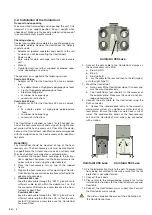
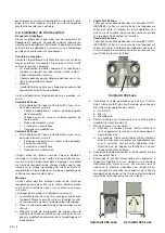
ComfoAir 350 Luxe
• The height when mounted should be at least 185cm,
beyond the space required for the duct connection.
ComfoAir 550 Luxe
• The height when mounted should be at least 173cm,
beyond the space required for the duct connection.
A 10mm gap should be left under the inside doors in order
to ensure effective and draught-free airflow in the house. If
these openings are obstructed, due to draught excluders
or deep-pile carpet, the airflow in the house will stagnate.
As a result, system performance will be compromised or
fail altogether.

