


II - IT
Sommario
Premessa
1.
Garanzia e responsabilità
...................................................................................................................1
2.
Norme di sicurezza
.............................................................................................................................1
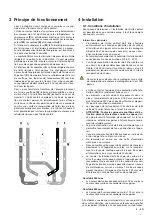
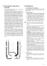
3
Presentazione generale e principio
...................................................................................................2
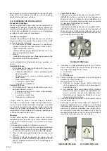
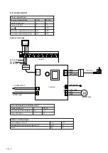
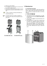
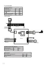
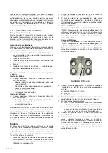
4 Installazione
........................................................................................................................................2
4.1. Condizioni di installazione .........................................................................................................2
4.2 Installazione dell ComfoCool .....................................................................................................3
5. Manutenzione .......................................................................................................................................4
5.1. Manutenzione periodica ............................................................................................................4
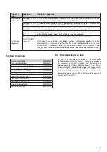
5.2. Guasti ...........................................................................................................................................5
5.3. Parti di ricambio ..........................................................................................................................6
5.4. Fine del ciclo di vita utile ............................................................................................................6
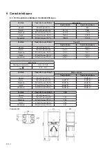
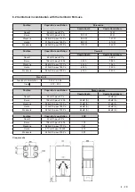
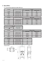
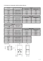
6. Specifiche .............................................................................................................................................7
6.1. ComfoCool abbinata ComfoAir 350 Luxe .................................................................................7
6.2. ComfoCool abbinata ComfoAir 550 Luxe .................................................................................8
6.3. Unità Comfort..............................................................................................................................9


