Handling and installation
While all equipment is designed for durability and
fabricated with heavy gauge materials and may
present a robust appearance, great care must be
taken to assure that no undue force is applied to
the coil, piping, drain connection or other delicate
components such as control boards during handling.
Wherever possible, all units should be maintained
in an upright position and handled by the chassis,
plenum sections or as close as possible to the
mounting points. In the case of a fully exposed
cabinet unit, the unit must obviously by handled by
the exterior casing. Gloves should be worn when
handling finished, painted units and should never be
set down on unclean, hard surfaces. Failure to follow
these instructions may lead to scratching or gouging
of the finished surface.
Although Zehnder Rittling does not become involved
with the design and selection of support methods
and/or components, it should be recognized that
unacceptable operating characteristics and/or
performance may result from poorly implemented
unit support. Additionally, proper clearance must be
provided for service and removal of the equipment.
Anchoring the equipment in place is accomplished by
using the mounting points provided, and positioning
the unit on a LEVEL plane. The drain pan is pitched
within the unit to provide proper drainage when the
unit is installed level. Care must be taken to ensure
that the drain pan does not slope away from the
drain connection. Vertical units are designed to be
bolted to the wall structure through the slotted wall
mounting holes in the chassis, used for anchoring
to pre-installed wall studs. Horizontal units are
provided with slotted ceiling mounting brackets where
hanging rod and rubber-in-shear or spring vibration
isolators, supplied by others, can be used for proper
suspension and vibration isolation.
The type of mounting device is a matter of choice,
however the mounting point should always be that
provided in the chassis, plenum or cabinet.
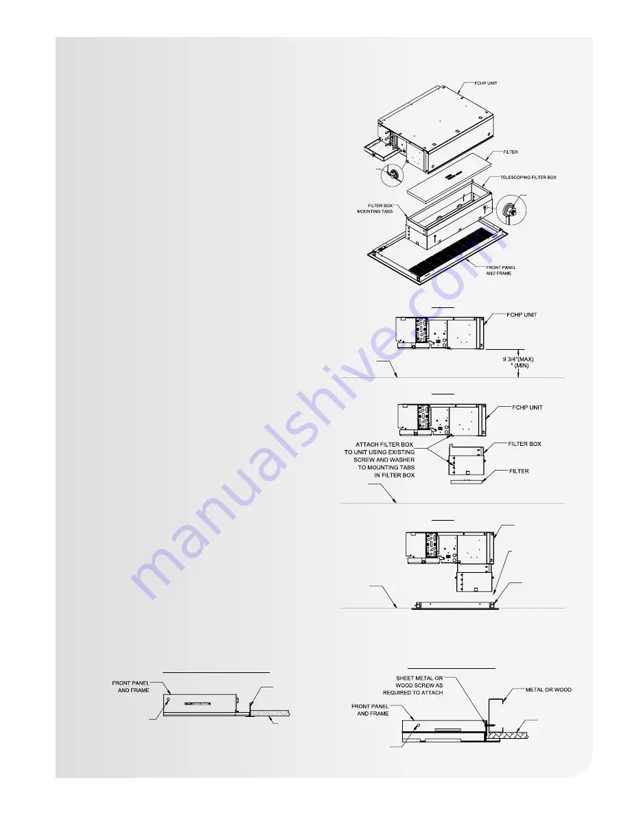
DRYWALL
CEILING STUD
STUD/DRYWALL CEILING SYSTEM
SUSPENDED GRID/TILE CEILING SYSTEM
CEILING
TILE
MOUNTING
HOLE
(SUSPENSION HARDWARE
BY OTHERS)
MOUNTING
HOLE
ATTACH TELESCOPING
FILTER BOX USING
EXISTING SCREW
AND WASHER IN
FCHP UNIT TO
MOUNTING TABS
IN FILTER BOX.
ADJUST HEIGHT
AFTER INSTALLATION
OF FRONT PANEL AND
FRAME TO PLACE
FILTER DIRECTLY
ABOVE AIR INLET.
CEILING TILE
GRID “T” BAR
(BY OTHERS)
STEP #1
STEP #2
STEP #3
FCHP UNIT
WITH FILTER
BOX ATTACHED
PANEL AND
FRAME
FINISHED
CEILING
FINISHED
CEILING
FINISHED
CEILING
7 1/8
LEAVE 1/8” - 1/4” GAP
BETWEEN FILTER
AND RETURN PANEL
FTHP Horizontal Fan Coil with telescoping bottom
panel assembly typical installation methods include:
25


