20 - EN
Assembly
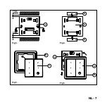
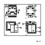
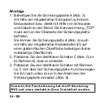
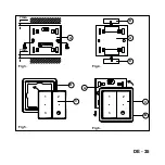
1. Use the screws supplied to fit locking plate A (fig.
3) to a flush outlet, or directly onto the wall using
the screws and plugs. The ‘TOP’ marking should be
visible at the top end of the locking plate.
You can also affix locking plate A (fig. 4) onto a
smooth/level surface (no metal surface) by means of
the self-adhesive strips (D).
2. Place cordless switch C (fig.5) into frame B, until it
clicks into position.
3. Place the cordless switch and frame approx. 5 mm
above locking plate A and lower it until it clicks tight
into the fastening lugs of the locking plate. (fig.6)
Note: The remote control is IP40 classified and
should therefore be fitted in zone 3.
Summary of Contents for RFZ
Page 4: ...4 NL Fig 1 Fig 2 ...
Page 7: ...NL 7 B C A C B 7 mm 7 mm A D D A Fig 3 Fig 5 Fig 4 Fig 6 1 2 3 1 2 3 ...
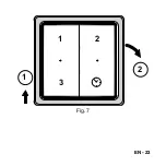
Page 9: ...NL 9 1 2 1 2 3 Fig 7 ...
Page 15: ...NL 15 ...
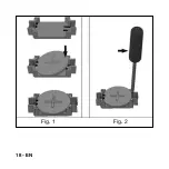
Page 18: ...18 EN Fig 1 Fig 2 ...
Page 21: ...EN 21 B C A C B 7 mm 7 mm A D D A Fig 3 Fig 5 Fig 4 Fig 6 1 2 3 1 2 3 ...
Page 23: ...EN 23 1 2 1 2 3 Fig 7 ...
Page 29: ...EN 29 ...
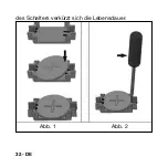
Page 32: ...32 DE des Schalters verkürzt sich die Lebensdauer Abb 1 Abb 2 ...
Page 35: ...DE 35 B C A C B 7 mm 7 mm A D D A Fig 3 Fig 5 Fig 4 Fig 6 1 2 3 1 2 3 ...
Page 37: ...DE 37 1 2 1 2 3 Abb 7 ...
Page 43: ...DE 43 ...
Page 46: ...46 FR Fig 1 Fig 2 ...
Page 49: ...FR 49 B C A C B 7 mm 7 mm A D D A Fig 3 Fig 5 Fig 4 Fig 6 1 2 3 1 2 3 ...
Page 51: ...FR 51 1 2 1 2 3 Fig 7 ...
Page 57: ...FR 57 ...
Page 60: ...60 IT Fig 1 Fig 2 ...
Page 63: ...IT 63 B C A C B 7 mm 7 mm A D D A Fig 3 Fig 5 Fig 4 Fig 6 1 2 3 1 2 3 ...
Page 65: ...IT 65 1 2 1 2 3 Fig 7 ...
Page 71: ...IT 71 ...
Page 74: ...74 PL ona używana tym krótszy jest okres eksploatacji Rys 1 Rys 2 ...
Page 77: ...PL 77 B C A C B 7 mm 7 mm A D D A Fig 3 Fig 5 Fig 4 Fig 6 1 2 3 1 2 3 ...
Page 79: ...PL 79 1 2 1 2 3 Rys 7 ...
Page 85: ...PL 85 ...
Page 86: ...86 PL ...
Page 87: ...PL 87 ...

