background image

Operation

14-Function Foot Control Panel, Wired or Wireless  

Version 6.1

Page 56

G-30-1706-en

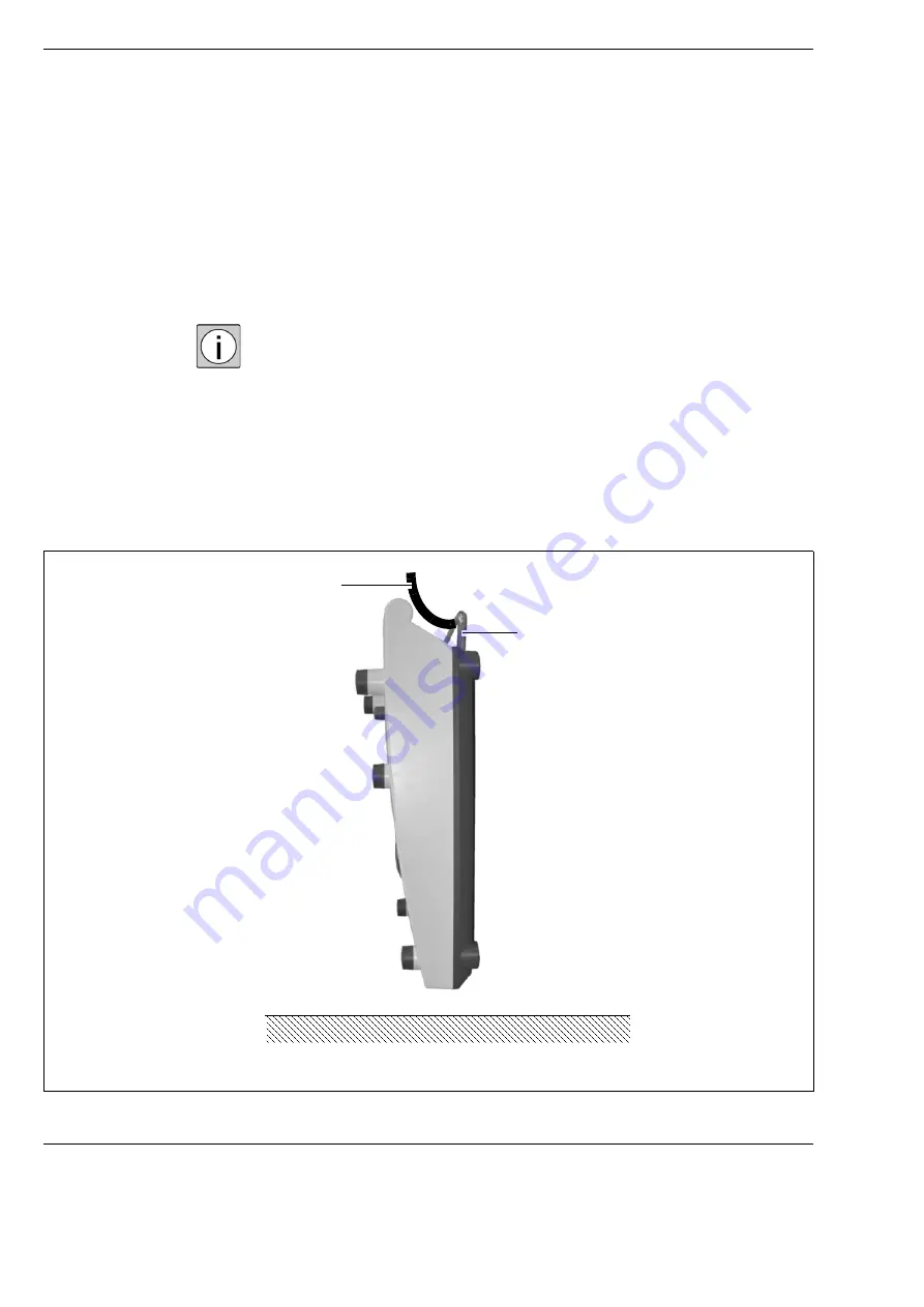
Rest position of the foot control panel

Place the foot control panel in the rest position by hanging on the 
mounting bracket (1), e.g. on the floor stand (2).

The foot control panel switches to rest position to save energy.

The energy-saving rest position extends the life cycle of the batteries in the 
wireless variant of the foot control panel.


2

1

Summary of Contents for 304970-9100-000

Page 1: ...ZEISS 14 Function Foot Control Panel Wired or Wireless Instructions for Use G 30 1706 en Version 6 1 2023 02 14...

Page 2: ...ill help you to search for specific terms Scope These instructions for use apply to the foot control panel with the following identification label Type label numbers 304970 9100 000 304970 9200 000 30...

Page 3: ...en Page 3 Section overview Section Safety measures 5 Section Layout and mode of functioning 19 Section Preparations for use 35 Section Operation 51 Section What to do in the event of malfunctions 57 S...

Page 4: ...14 Function Foot Control Panel Wired or Wireless Version 6 1 Page 4 G 30 1706 en...

Page 5: ...important information concerning matters relevant to instrument safety Explanation of the symbols in these Instructions for Use 6 Hazard symbols 6 Information symbols 6 Obvious misuse 6 Notes for the...

Page 6: ...or an action Prompt for an action Result of an action Additional information and tips These do not contain any warnings of dangers Obvious misuse Operation of the foot control panel with devices not m...

Page 7: ...to reduce the residual risks for users and patients to a minimum Proper use Both the wired and wireless variants of the 14 function foot control panel are designed to enable the hands free control of...

Page 8: ...urpose only Operate the foot control panel only with the components included in the delivery package If you wish to use other components check beforehand that the safe use of these components has been...

Page 9: ...uses interference with radio and TV reception which can be determined by turning the component off and on the user should try to correct the interference by one or several of the following measures Re...

Page 10: ...ble at all times for the operating personnel Modifications and repairs of the foot control panel and components operated together with it may only be performed by our Service representative or by othe...

Page 11: ...ew connections have been firmly tightened All cables and plugs are in perfect condition i e without signs of wear kinks or other damage Before every use Make sure that all specified Requirements for o...

Page 12: ...Risk of injury due to illegible labels Over time labels can become dirty or unidentifiable making it difficult or impossible for hazards to be recognized or necessary operating instructions to be foll...

Page 13: ...tructions for use or accompanying documents 3 Observe disposal regulations indicating label Do not dispose of electrical or electronic devices along with normal domestic waste For more information on...

Page 14: ...ncy approval labeling on the base of the stand See also document G 30 2021 Radio Approval Information Non ionizing electromagnetic radiation MIC labeling NOM ANCE labelling KC labelling 10 Pairing sig...

Page 15: ...Version 6 1 G 30 1706 en Page 15 14 Function Foot Control Panel Wired or Wireless Safety measures 1 A 1 B 2 3 4 8 7 5 10 9 6 11...

Page 16: ...multipoint connector on the stand 9 Identification label The labeling signs contain the following information Manufacturer Manufacturer s name Manufacturer s address Serial number Device name version...

Page 17: ...c devices along with normal domestic waste For more information on the disposal of electrical and electronic devices please see the chapter Maintenance and care 12 Observe Instructions for Use indicat...

Page 18: ...Safety measures 14 Function Foot Control Panel Wired or Wireless Version 6 1 Page 18 G 30 1706 en...

Page 19: ...ioning Layout and mode of functioning Design variants of the foot control panel 21 Components of the foot control panel 22 Standard configuration with lengthwise orientation 26 Standard configuration...

Page 20: ...Layout and mode of functioning 14 Function Foot Control Panel Wired or Wireless Version 6 1 Page 20 G 30 1706 en...

Page 21: ...Control Panel Wired or Wireless Layout and mode of functioning Design variants of the foot control panel 1 Wireless foot control panel with 14 functions aerial view 2 Wired 14 function foot control pa...

Page 22: ...Operate the Zoom and Focus functions using the two rocker switches The rocker switches contain two buttons each for this purpose For example you can operate the buttons in the rocker switches using t...

Page 23: ...14 Function Foot Control Panel Wired or Wireless Layout and mode of functioning 8 Status indicators Show various types of status by being illuminated or not illuminated 5 M B Zoom Focus Focus Zoom 1...

Page 24: ...he foot control panel is not ready for use there is an error 2 Connection status indicator Not shining the foot control panel is operating in wireless mode Shining green The connecting cable if provid...

Page 25: ...r Wireless Layout and mode of functioning Functions of the audible information signals Audible information signal Cause Corrective measure One beep Confirms a function Two beeps Warning Query the stat...

Page 26: ...ction depending on surgical microscope 7 Focus down Focus a lower level reduces working distance 8 Focus up Focus a higher level increases working distance 9 Button Function depending on surgical micr...

Page 27: ...Version 6 1 G 30 1706 en Page 27 14 Function Foot Control Panel Wired or Wireless Layout and mode of functioning 6 7 8 11 12 13 14 5 10 9 1 2 4 3...

Page 28: ...n depending on surgical microscope 7 Focus down Focus a higher level reduces working distance 8 Focus up Focus a higher level increases working distance 9 Button Function depending on surgical microsc...

Page 29: ...Version 6 1 G 30 1706 en Page 29 14 Function Foot Control Panel Wired or Wireless Layout and mode of functioning 1 6 7 9 12 8 13 14 5 11 10 2 4 3...

Page 30: ...e for pressure equalization of the FCP 1 Membrane for pressure equalization of the FCP The foot control panel is built with protection class IPX8 A membrane is installed so that pressure equalization...

Page 31: ...Version 6 1 G 30 1706 en Page 31 14 Function Foot Control Panel Wired or Wireless Layout and mode of functioning...

Page 32: ...switch upward using a small screwdriver 3 Ready for use status indicator Shining green The foot control panel is ready for use there are no errors Shining orange The foot control panel has detected a...

Page 33: ...el Flashing in orange while pairing with the suspension system is in progress 6 Battery status indicator Not shining batteries are OK Shining orange batteries are running out No immediate action requi...

Page 34: ...Layout and mode of functioning 14 Function Foot Control Panel Wired or Wireless Version 6 1 Page 34 G 30 1706 en...

Page 35: ...r use Preparations for use Installing FCP upgrade kit optional 36 Plug in upgrade kit 36 Insert batteries for wireless operation 38 Pairing with the stand FCP upgrade kit optional 40 Plug in connectio...

Page 36: ...f Connect the head 1 to the counterpart 3 of the multipoint connector Push the FCP upgrade kit 2 into the multipoint connector 5 until the FCP upgrade kit audibly clicks in The FCP upgrade kit is in w...

Page 37: ...Version 6 1 G 30 1706 en Page 37 14 Function Foot Control Panel Wired or Wireless Preparations for use 1 5 6 3 4 2 1...

Page 38: ...is correct by checking the floor of the battery compartment 3 Close the cover of the battery compartment 2 Rotate both interlocks 1 on the battery compartment from the 9 o clock position to the 12 o...

Page 39: ...Version 6 1 G 30 1706 en Page 39 14 Function Foot Control Panel Wired or Wireless Preparations for use 1 2 3...

Page 40: ...g the pairing process on the stand wait at least 10 seconds before performing any further steps on the FCP on the FCP upgrade kit optional Delete the existing pairing by pushing the Pairing button 9 o...

Page 41: ...starts to flash in orange Release the button 3 on the foot control panel The Radio link intensity status indicator 7 on the foot control panel flashes in orange for a few more seconds on the FCP upgr...

Page 42: ...y pressing two buttons at the same time The Radio link intensity status indicator 7 then lights up Pairing failed If three beeps sound this indicates that pairing was not completed successfully The Ra...

Page 43: ...Version 6 1 G 30 1706 en Page 43 14 Function Foot Control Panel Wired or Wireless Preparations for use 1 9 7 7 3 3 3 3 3 3 4 6 5 6 2 5 8 8...

Page 44: ...e to loops in the connection cable Check how the connection cable if available is laid Remove loops and lay the connection cable so that there are no tripping hazards NOTE Use of systems for microwave...

Page 45: ...Foot Control Panel Wired or Wireless Preparations for use Insert the 6 pin plug 1 into the socket of the foot control panel 3 Insert the 4 pin plug 2 straight or angled into the socket 4 on the stand...

Page 46: ...Preparations for use 14 Function Foot Control Panel Wired or Wireless Version 6 1 Page 46 G 30 1706 en...

Page 47: ...livery package of the foot control panel contains an extension for thejoystick and a joystick mushroom cap You may use these in accordance with your mode of working Pull the extension on the joystick...

Page 48: ...control panel is non operational in rest position Energy management switches to operating mode 4 or 5 see page 54 to save energy If the foot control panel is placed in working position after an extend...

Page 49: ...Version 6 1 G 30 1706 en Page 49 14 Function Foot Control Panel Wired or Wireless Preparations for use 1 2 0 10 90 45 4 5 3 4 5 3...

Page 50: ...Preparations for use 14 Function Foot Control Panel Wired or Wireless Version 6 1 Page 50 G 30 1706 en...

Page 51: ...Foot Control Panel Wired or Wireless Operation Operation Wireless foot control panel checklist 52 Wired foot control panel checklist 53 Foot control panel operating modes 54 Remove connection cable 5...

Page 52: ...l functions of the foot control panel Stand and surgical microscope must react properly when controlled via the foot control panel CAUTION Failure of functions For safety reasons do not use this foot...

Page 53: ...igured Check all functions of the foot control panel Stand and surgical microscope must react properly when controlled via the foot control panel CAUTION Failure of functions For safety reasons do not...

Page 54: ...erating mode 1 The table below shows you the various operating modes Mode Conduct on operation Duration inactive until transition to next mode 1 Command is carried out with a delay of max 100 ms 10 s...

Page 55: ...be installed before the stand is switched on otherwise the stand does not recognize the FCP upgrade kit The FCP upgrade kit optional must remain on the stand while the foot control panel is in use Re...

Page 56: ...control panel Place the foot control panel in the rest position by hanging on the mounting bracket 1 e g on the floor stand 2 The foot control panel switches to rest position to save energy The energ...

Page 57: ...nctions What to do in the event of malfunctions What to do ifthe wireless foot control panel fails 58 Wireless foot control panel troubleshooting 60 For your safety 60 Malfunctions on the foot control...

Page 58: ...e the following steps first Insert the 6 pin connector 1 of the connecting cable if provided in socket 3 on the foot control panel Insert the 4 pin connector 2 straight or angled of the connecting cab...

Page 59: ...Version 6 1 G 30 1706 en Page 59 14 Function Foot Control Panel Wired or Wireless What to do in the event of malfunctions 1 3 2 1 4...

Page 60: ...fe working order we recommend having it checked by our service representative as part of regular scheduled maintenance If a failure occurs which you cannot correct with the aid of the chapter What to...

Page 61: ...on differently this is possible only if the functions on the stand are configurable Call Service Failure fault of the radio link for the wireless foot control panel Establish cable connection if conne...

Page 62: ...d are configurable Call Service Page 11 Foot switch panel sends erroneous activation signal Move foot switch panel to the rest position Configure button function differently this is possible only if t...

Page 63: ...hat to do in the event of malfunctions attach a sign to the system stating it is out of order and contact our service representative Malfunctions on the foot control panel The state indications and th...

Page 64: ...able connection on the stand optionally on the FCP upgrade kit Configure button function differently this is possible only if the functions on the stand are configurable Call Service Page 44 Foot swit...

Page 65: ...1706 en Page 65 14 Function Foot Control Panel Wired or Wireless Care and Maintenance Care and Maintenance Care of the device 66 Cleaning 66 Disinfection 67 Environmental protection measures 68 Notes...

Page 66: ...use where possible In order to keep cleaning and disinfection from being too difficult contaminants should not be allowed to dry on the objects Cleaning mechanical surfaces All mechanical surfaces of...

Page 67: ...han 70 can be used to achieve maximum disinfection There is a chance that long term use of such disinfectants may cause the device s surfaces to become dull or matte or may loosen the adhesive labels...

Page 68: ...of the product or its components the seller is required to inform the buyer that the product must be disposed of in accordance with the applicable national regulations currently in force For customers...

Page 69: ...G 30 1706 en Page 69 14 Function Foot Control Panel Wired or Wireless Device data Device data Specifications 70 Mechanics 70 Electrical system 70 Ordering data 73 Regulatory information 74 Ambient co...

Page 70: ...Weight of foot control panel without batteries Approx 2 8 kg Weight of FCP upgrade kit Approx 243 g Component Feature Power supply 3 x 1 5 V type C baby cell alkaline manganese batteries Current Cons...

Page 71: ...ried out via stand Current Consumption max 400 mA Electrical standard In accordance with IEC 60601 1 UL 60601 1 Protection class IPX8 Cable connector Remote socket for connecting cable The device is d...

Page 72: ...h systems with which the FCP WL 304970 9200 000 is used Please contact your ZEISS partner if you wish to retrofit the FCP WL 2 to work with an existing system Component Properties Radio spectrum 2402...

Page 73: ...unction foot control panel wireless FCP WL 2 304972 9200 000 Joystick mushroom cap 304970 8807 000 Joystick extension 304970 8808 000 3 m connecting cable for 14 function foot control panel FCP FCP WL...

Page 74: ...pprovals See also document G 30 2021 Radio Approval Information The radio frequency approvals apply only to the wireless version of the foot control panel Feature Admissible range Temperature 10 C 40...

Page 75: ...ndicates the correct upright position of the package Fragile handle with care Keep dry Permissible temperature range Limit of storage operating temperature Specification of the number of packing units...

Page 76: ...Device data 14 Function Foot Control Panel Wired or Wireless Version 6 1 Page 76 G 30 1706 en...

Page 77: ...attery compartment 38 Battery disposal 68 Battery type 38 Beep 25 Buttons 22 C Care 65 Changing 68 Cleaning 66 Connection cable 22 Connection cable not plugged in 63 Current consumption 70 D Directive...

Page 78: ...2 47 L Longitudinal orientation 22 26 M Maintenance 65 Malfunction 61 63 Malfunction during use of multiple foot control panels 42 Manufacturer s address 2 Manufacturer s information 2 Membrane for pr...

Page 79: ...ife of batteries 70 Standards 6 Status indicator 23 24 Symbols and labels 12 T Target group 6 Technical specifications 70 Transverse orientation 22 28 U Use of several foot control panels 42 W What to...

Page 80: ...Index 14 Function Foot Control Panel Wired or Wireless Version 6 1 Page 80 G 30 1706 en...

Page 81: ...Version 6 1 G 30 1706 en Page 81 14 Function Foot Control Panel Wired or Wireless Blank page for your notes...

Page 82: ...Carl Zeiss Meditec AG Goeschwitzer Strasse 51 52 07745 Jena Germany Email info meditec zeiss com Internet www zeiss com med Instructions for use www zeiss com ifu...

Reviews: